Voltage Division Rule: A Practical, Down-to-Earth Guide for Real Engineers (and Anyone Curious Enough to Learn It)
If you’ve ever held a multimeter in your hand and wondered why a circuit stubbornly refuses to give the voltage you expect, you’re in good company. Most of us—whether we’re technicians, students, or seasoned engineers—have had that moment where a “simple” pair of resistors behaves in a way that feels anything but simple. You might even catch yourself thinking, “Isn’t the voltage division rule supposed to be the easy part?”
Well, yes… and no.
The idea is straightforward, but the real world tends to sprinkle in a few complications: loading effects, resistor tolerances, temperature drift, noisy supplies, unexpected current draw, and that one coworker who insists on using a voltage divider as a power supply (please don’t do this). This article walks you through everything—from the “explain it to your younger self” version to the more rigorous engineering treatment—so you understand not just how voltage division works, but when it works and why.
And most importantly, you’ll walk away knowing how to apply it confidently in your own projects, whether you’re conditioning a small sensor signal or analyzing voltage division in an AC circuit.
What the Voltage Divider Really Is (Let’s Start Simple)
Imagine you’re standing at the top of a hill with a bucket of water. The water represents voltage—the “potential” to do something. Now imagine there’s a long path down the hill with two gates that restrict how fast water flows. The gates represent resistors. The tighter the gate, the more pressure builds behind it. The looser the gate, the less pressure.
That’s almost exactly what happens in a voltage divider. Each resistor in series takes a share of the “pressure” (voltage), and the size of the share depends on how large that resistor is compared to the total.
You don’t need calculus or circuit theory to get the intuition: larger resistor → larger share. Smaller resistor → smaller share.
But of course, at some point we need to stop imagining gates and water and go back to real circuits.
To make things simpler, assume that we have a simple circuit consisting of a voltage source and several resistors. This circuit can be solved easily with an Ohm’s Law.
The voltage drop across each resistor is proportional to the ohmic value of the resistor.
The current flowing in the circuit is proportional to the total resistance of all the resistors in that circuit.
Using the Ohm’s Law, we can calculate the voltage drop across each resistor as
\( V = I \times R \)
The voltage across a resistor is equal to the current flowing in the circuit multiplied by the resistance.
Formal Definition (Because We’re Professionals Too)
A voltage divider is a series network of two (or more) resistors with an input voltage applied across the entire chain. The voltage across any individual resistor is proportional to its resistance.
This rule is rooted in Ohm’s Law and basic circuit theory—nothing exotic, nothing new. Standards such as IEC 60038 don’t define the concept directly (it’s too fundamental), but the principle is consistent with all established electrical theory.
Here’s the formula you’ve probably seen before, but let’s restate it cleanly:
\( V_{\mbox{out}}=V_{\mbox{in}}\times \frac{R_2}{R_1 + R_2} \)
Where:
- \( V_{\mbox{in}} \) is the total input voltage
- \( R_1 \) is the resistor connected to the input
- \( R_2 \) is the resistor connected to ground
- \( V_{\mbox{out}} \) is the voltage across \( R_2 \)
It’s deceivingly simple… and that’s exactly why people misuse it.
Voltage division rule is very popular since voltage divider circuit is widely used for many applications. We can divide a voltage level into a specific percentage of the maximum voltage only by using the correct resistors.
The voltage division rule states that:
The entire voltage supplied across a series connection of numerous resistors is proportionally divided across the resistors.
This shows that the greatest voltage drop will be found across the resistor with the highest resistance. Opposite of that, the smallest voltage drop will be found across the resistor with the lowest resistance.
This voltage division rule is true for both AC circuits and DC circuits.
Keep in mind that we use impedance instead of resistance when dealing with an AC circuit.
Voltage Division in AC Circuits (Same Idea, Just More Interesting)
Once AC enters the picture, resistors stop being the full story. Capacitors and inductors come into play, and at that point we use impedance (Z) instead of resistance (R).
The formula becomes:
\( V_x = V_{\mbox{in}} \times \frac{Z_x}{Z_{\mbox{total}}} \)
This matters in:
- audio filtering
- amplifier biasing
- AC metering
- sensor excitation circuits
- RC and RL filters
- power electronics signal conditioning
If you’re ever unsure whether to use R or Z, just ask yourself: Is this AC, or is there a capacitor/inductor nearby? If yes, use impedance.
Why Not Use a Voltage Divider as a Power Supply? (Seriously, Don’t)
This question pops up so often that entire forum threads are dedicated to it. So let’s be direct.
A voltage divider is not a power supply because:
- Its output voltage collapses with load.
- Its current draw is continuous and wasteful.
- It violates good engineering practice and most safety expectations.
- Its load regulation is terrible—even tiny load changes can swing output voltage wildly.
- It’s dangerously unreliable for anything that consumes variable current.
Voltage Divider Rule Formula
Our objective here is to be able to calculate the voltage across a specific resistor.
Before understanding why voltage is divided in series circuits, we need to understand the relationship between the voltage, current, and resistance in a series connection.
Observe a simple circuit below with \( n \) resistors.
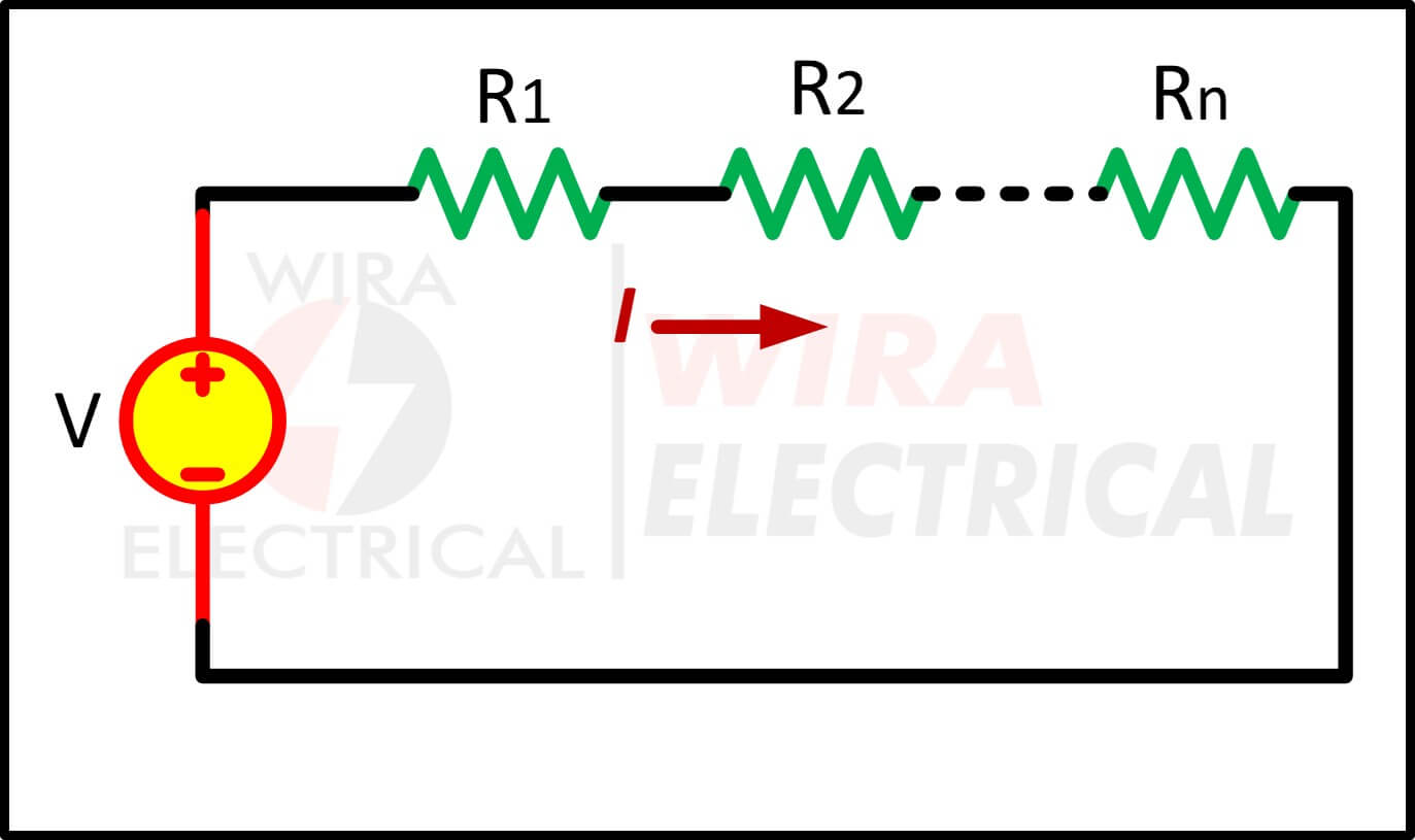
The total resistance in that circuit is
\( R_{eq} = R_1 + R_2 + … + R_n \)
The total current flowing in the circuit is
\( I = \frac{V}{R_{eq}} \)
This is where we use Ohm’s Law to calculate the voltage across a specific resistor. The voltage across resistor R1 will be
\( V_1 = I \times R_1 \)
The voltage across resistor R2 will be
\( V_2 = I \times R_2 \)
The voltage across the Rn will be
\( V_n = I \times R_n \)
Now, substituting the total current equation with the voltage across R1 will give us
\( V_1 = V \times \frac{R_1}{R_{eq}} \)
Substituting the total current equation with the voltage across R2 will give us
\( V_2 = V \times \frac{R_2}{R_{eq}} \)
Substituting the total current equation with the voltage across Rn will give us
\( V_n = V \times \frac{R_n}{R_{eq}} \)
Where:
\( V_n \) = voltage drop across the n-th resistor
\( R_n \) = resistance of the n-th resistor
The sum of the voltage drop across the n series resistors is equal to the ratio of total current divided by equivalent resistance of the resistors.
We can conclude that:
The voltage drop across an n-th resistor is the product between input voltage and the resistance of the n-th resistor divided by the equivalent series resistance.
This answers the question of why voltage is divided in series circuits. It is because the current in a series circuit is constant through every resistor while the voltage across each resistor depends on its resistance.
Voltage Divider Rule Formula in Series Circuit
A voltage divider draws current continuously:
\( I = \frac{V_{in}}{R_1 + R_2} \)
This current does nothing except produce heat. It’s the price you pay for obtaining a fraction of the input voltage.
In professional design work, there’s a rule of thumb:
- Divider current should be ≥10× the current drawn by the load
- For high accuracy, ≥100× is preferred
- For ultra-low-power designs (e.g., battery monitors), you deliberately choose much higher resistances to waste less energy
Choosing resistor values is a balancing act between accuracy, noise immunity, and power efficiency.
Let us do one more calculation and try to understand it fully.
Observe a simple circuit below consisting of a voltage source and three resistors connected in series.
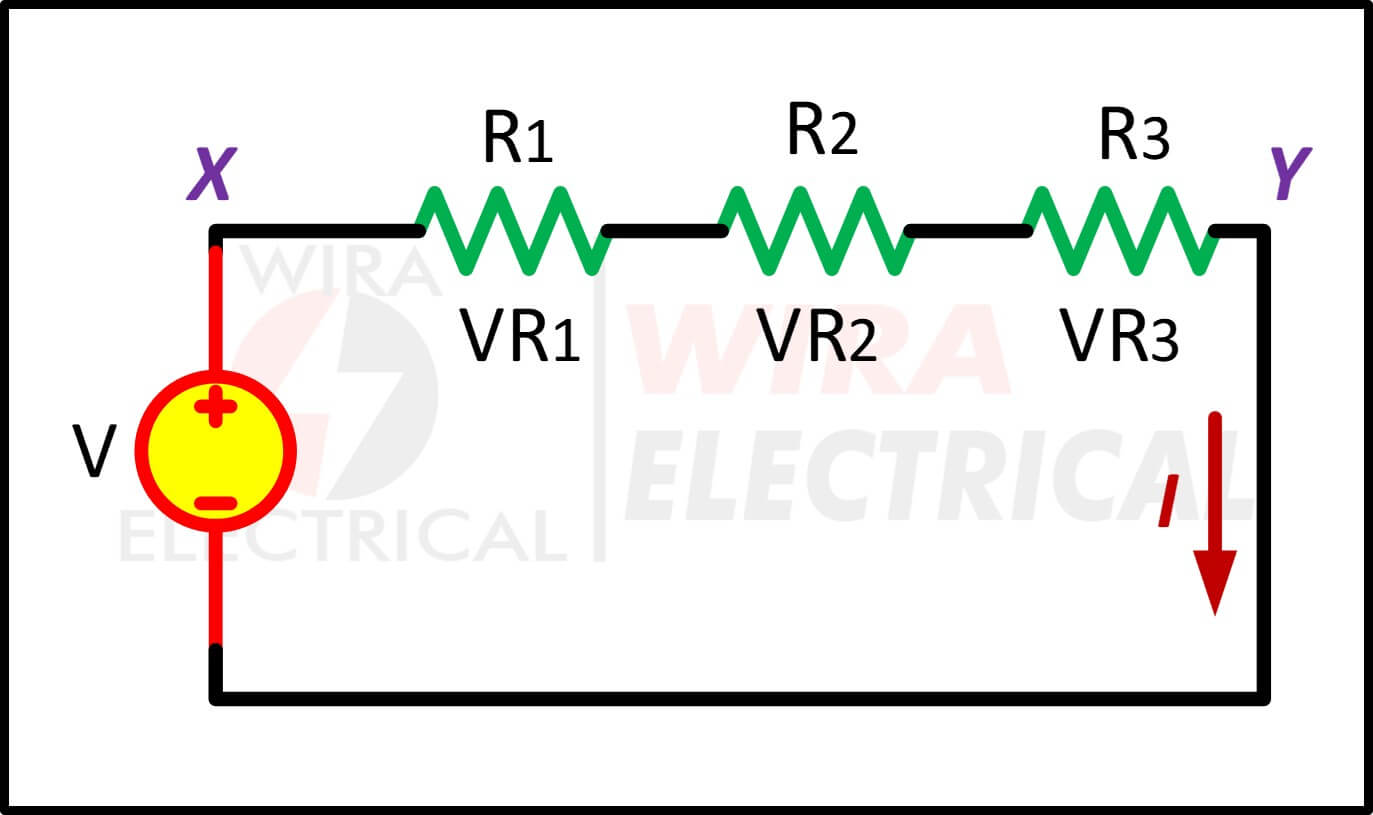
We are now looking for the voltage drop \( V_{R1} \), \( V_{R2} \), and \( V_{R3} \) for each resistor \( R_1 \), \( R_2 \), and \( R_3 \) respectively.
Since the current is equal through each resistor, the voltage drop should only be affected by the resistance value.
How to find individual voltage in a series circuit? Simply by using Ohm’s Law for each resistor will solve this question. The voltage drop are
$$
\begin{aligned}
V_{R1} &= I \times R_1 \\
V_{R2} &= I \times R_2 \\
V_{R3} &= I \times R_3
\end{aligned}
$$
The total voltage across node X – Y must equal to the sum of the voltage drops across each resistor. As a result we can write:
\( V = V_{R1} + V_{R2} + V_{R3} \)
Substituting each voltage drop with the equation before will give us
$$
\begin{aligned}
V &= I(R_1 + R_2 + R_3)\\
I &= \frac{V}{R_1 + R_2 + R_3}
\end{aligned}
$$
The voltage distribution across the individual resistor can be calculated below
$$
\begin{aligned}
V_{R1} &= V \frac{R_1}{R_1 + R_2 + R_3} \\
V_{R2} &= V \frac{R_2}{R_1 + R_2 + R_3} \\
V_{R3} &= V \frac{R_3}{R_1 + R_2 + R_3}
\end{aligned}
$$
How does voltage split in series?
The voltage distribution was estimated using three resistors in series, the method can be used with any number of series connected resistors in a DC circuit or impedance in AC circuit.
\( V_{Rn} = V \frac{R_n}{R_1 + R_2 + R_3} \)
Keep in mind that we need to calculate the entire resistance into an equivalent resistance even if we only want to calculate a single voltage drop.
Voltage Divider Circuit and Voltage Divider Resistor Selection
Voltage divider circuit is a circuit to produce the desired voltage level from the voltage source but the current is still the same. The common configuration of a voltage divider circuit is shown below.
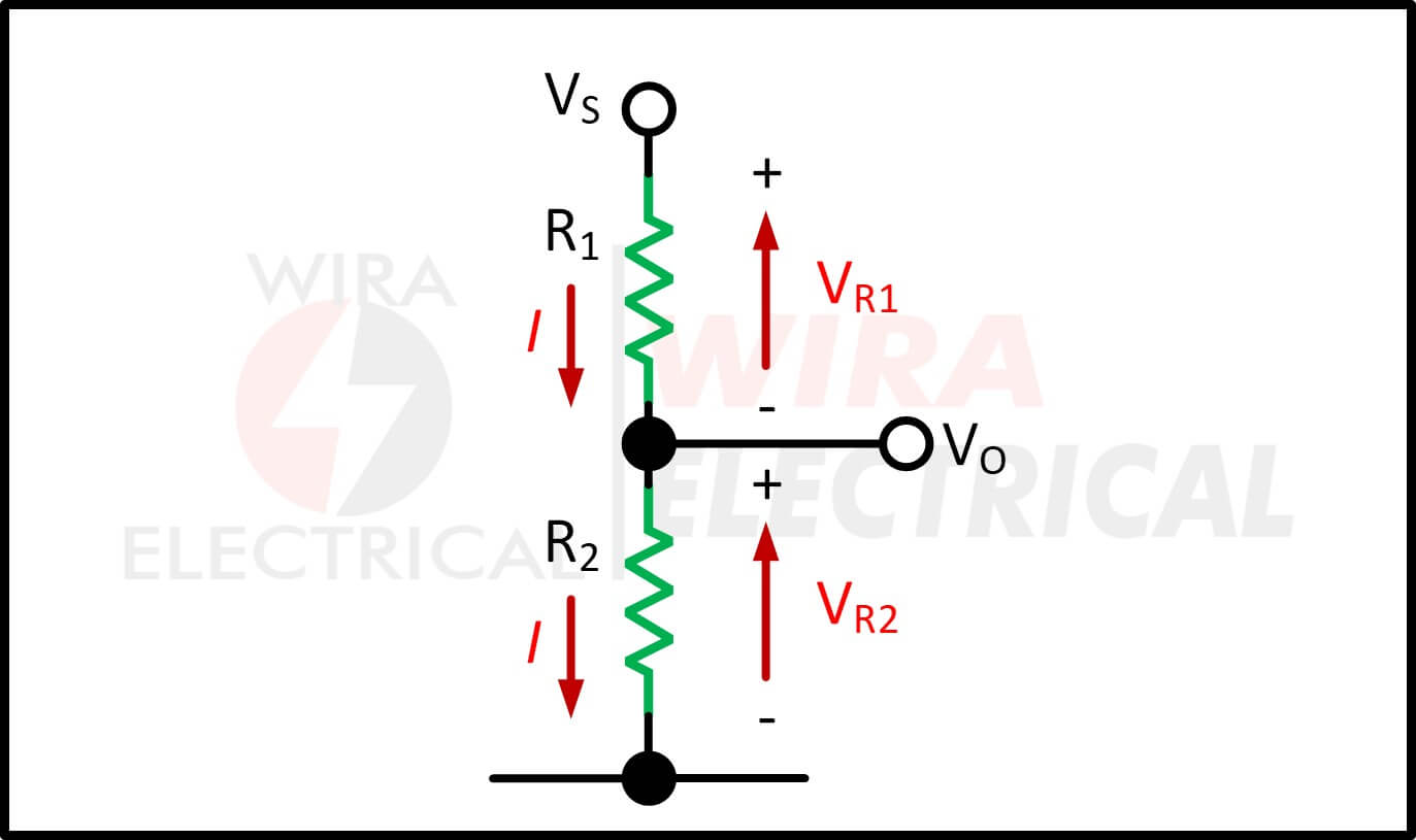
Voltage divider circuit only purpose is to divide the voltage source into different voltage levels with respect to the ground.
Since voltage is also known as potential difference, a voltage divider is also known as potential divider.
The voltage source \( V_s \) is applied to the entire series resistors and we can use Kirchhoff’s Voltage Law and Ohm’s Law to calculate the voltage drop across the desired resistor.
The voltage drop across \( R1 \) is
$$
\begin{aligned}
I_{R1}&=\frac{V_{R1}}{R_1}=\frac{V_S}{(R_1 + R_2)}\\
V_{R1}&=V_S(\frac{R_1}{R_1+R_2})
\end{aligned}
$$
The voltage drop across the \( R_2 \) is
$$
\begin{aligned}
I_{R2}&=\frac{V_{R2}}{R_2}=\frac{V_S}{(R_1 + R_2)}\\
V_{R2}&=V_S(\frac{R_2}{R_1+R_2})
\end{aligned}
$$
To simplify the equation, the voltage divider equation is
\( V_{Rn}=V_S(\frac{R_n}{R_{\mbox{eq}}}) \)
Where Vn is the voltage drop across the n-th resistor, \( V_s \) is the voltage source, Rn is the resistance of the n-th resistor, and Req is the equivalent series resistance.
Picking resistor values is where theory meets reality. Here’s how to do it without overthinking:
1. Start With Total Resistance
Common total resistance ranges:
Application | Typical R₁+R₂ |
General analog work | 10 kΩ–50 kΩ |
Microcontroller ADC inputs | 10 kΩ–200 kΩ |
Low-noise or high-speed | 1 kΩ–10 kΩ |
Battery voltage monitoring | 100 kΩ–1 MΩ |
2. Account for the Load Resistance
If your load resistance is close in value to your divider, the output voltage will sag.
Always check the input impedance of:
- ADC pins
- instrument amplifiers
- comparators
- microcontroller inputs
- sensor interfaces
A divider works best when the load impedance is much higher (10×–100×) than the divider’s lower leg resistor.
3. Mind the Tolerances
A 5% resistor can completely throw off precision measurements.
Go with 1% or 0.1% if accuracy matters.
4. Check Power Dissipation
Always check:
\( P = I^2 R \)
Especially if you’re dividing high voltages (e.g., mains-level sensing with megohm ranges).
How to Use the Voltage Division Rule (A Complete Walkthrough)
Let’s go through a realistic example. This is the kind of thing you actually encounter during design work.
Goal:
Take 12 V and bring it down to 3 V for an ADC.
Step 1: Ratio
You want:
\( \frac{V_{\mbox{out}}}{V_{\mbox{in}}}=0.25 \)
Pick:
\( R_1 = 30k \Omega, R_2 = 10 k\Omega \)
Step 2: Divider Current
\( I = \frac{12}{40k\Omega}=0.3 mA \)
This is light and safe.
Step 3: Check Load Effect
If your ADC input impedance is 1 MΩ, then:
\( R_{\mbox{parallel}}=\frac{1M\Omega \times 10 k\Omega}{1M\Omega + 10 k\Omega} \approx 9.9k\Omega \)
That’s barely a change.
Your reading will be accurate.
Step 4: Confirm Power Dissipation
\( P = I^2 R_1 \approx 0.003 W \)
A standard 1/4-W resistor is overkill.
You’re good.
Voltage Division Rule Formula Examples
Now let us solve some examples
- Calculate the voltage drops in the circuit below consists of 2 resistors connected in series
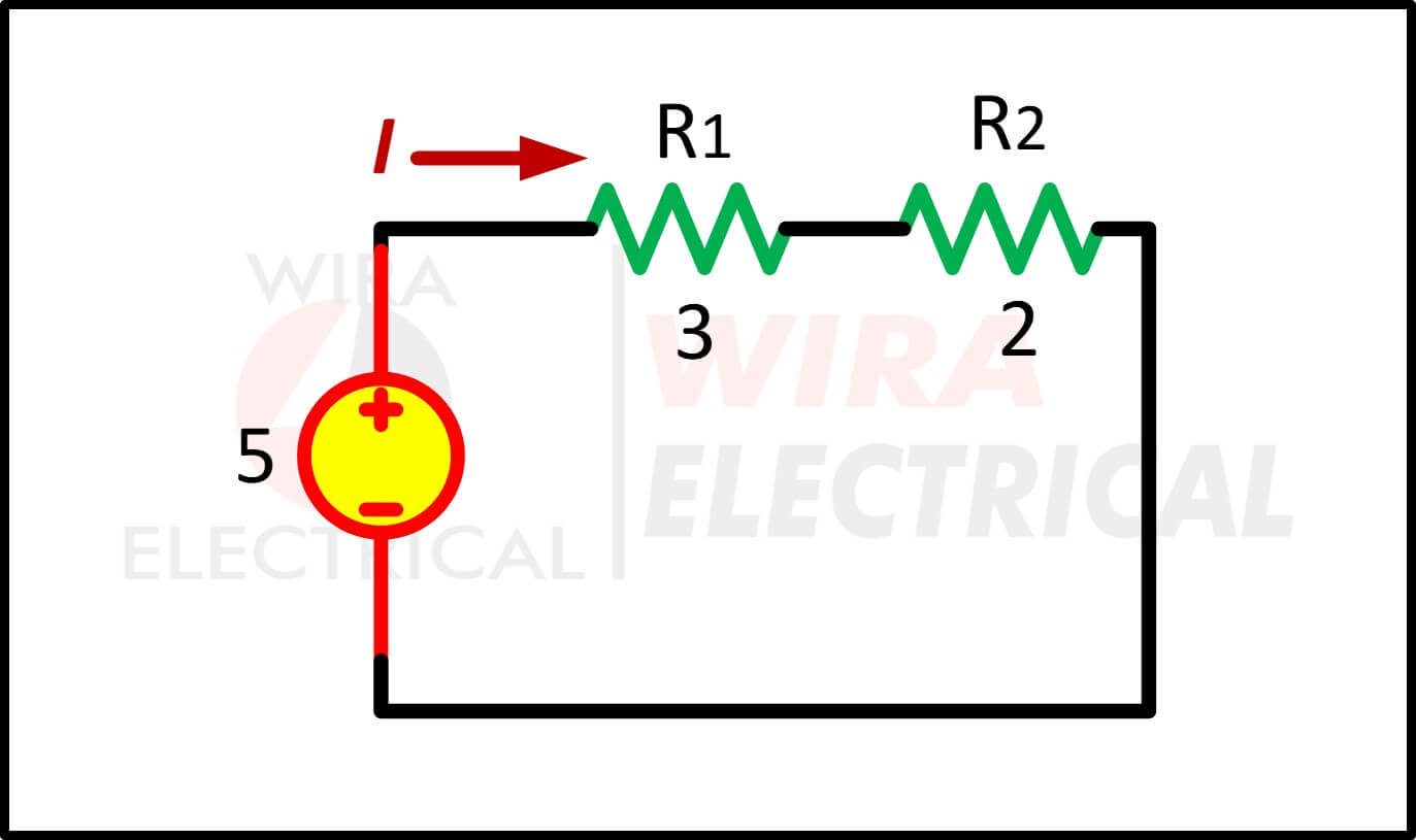
The total resistance or equivalent resistance is
$$
\begin{aligned}
R_{eq}&= R_1 + R_2 \\
&=3 + 2 \\
&=5\Omega
\end{aligned}
$$
The total current is
$$
\begin{aligned}
I &= \frac{V}{R_{eq}}\\
&= \frac{5}{5} = 1 A
\end{aligned}
$$
The voltage drop across the \( R_1 \) is
$$
\begin{aligned}
V_1 &= I \times R_1 \\
&= V \times \frac{R_1}{R_{eq}} \\
&= 5 \times \frac{3}{5} = 3V
\end{aligned}
$$
The voltage drop across the \( R_2 \) is
$$
\begin{aligned}
V_2 &= I \times R_2 \\
&= V \times \frac{R_2}{R_{eq}} \\
&= 5 \times \frac{2}{5} = 2V
\end{aligned}
$$
- An electrical circuit below consists of 3 resistors with the same resistance. Calculate the voltage drop across each resistor
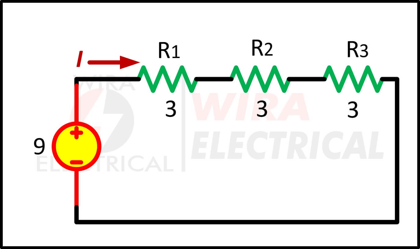
The equivalent resistance is
$$
\begin{aligned}
R_{eq}&=R_1 + R_2 + R_3 \\
&=3+3+3 \\
&=9 \Omega
\end{aligned}
$$
The total current is
\( I = \frac{V}{R_{eq}}=\frac{9}{9}=1A \)
The voltage drop across each resistor is
$$
\begin{aligned}
V_1 = V_2 = V_3 &= V \times \frac{R_1}{R_{eq}}\\
&= 9 \times \frac{3}{9}\\
&= 3V
\end{aligned}
$$
- Below is the common voltage divider circuit only with two resistors. We will get the desired voltage at the VOUT terminal.
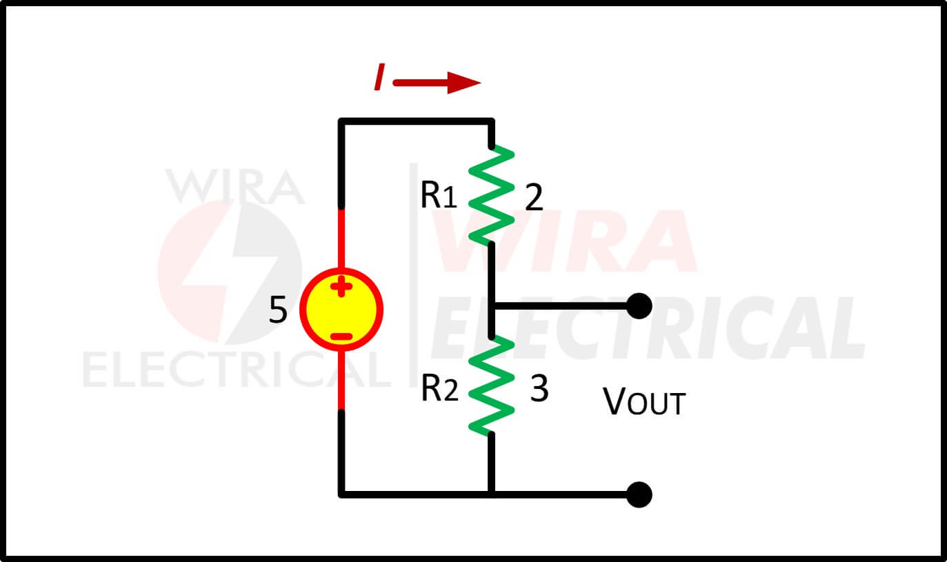
Straight to our point, the VOUT will be
$$
\begin{aligned}
V_{OUT}&= V_2\\
&= V \times \frac{R_2}{R_1 + R_2}\\
&= 5 \times \frac{3}{5} \\
&= 3V
\end{aligned}
$$
Using Voltage Dividers for Sensor Measurement (One of the Most Common Applications)
If you’ve ever built a sensor interface, you’ve probably used a voltage divider without even thinking about it. Thermistors, LDRs, pressure sensors, and many other components act like variable resistors. Pair them with a fixed resistor and—bam—you have an analog voltage that varies with temperature, light, pressure, and so on.
When you use a voltage divider for sensor measurement, here’s what to watch out for:
- The sensor’s resistance range
- The linearity (or lack of it)
- The desired output swing
- The supply voltage stability
- Tolerance and temperature drift
For example, NTC thermistors are highly nonlinear. You can linearize them around a temperature range by choosing the right fixed resistor. It’s a trick used in HVAC systems everywhere.
Real-World Voltage Divider Applications
Voltage dividers are everywhere. Once you start looking for them, you’ll see them in:
1. Microcontroller ADC Scaling
Converting 24 V, 12 V, or 5 V to 3.3 V safely.
2. Transistor Bias Networks
Setting a stable base or gate voltage in amplifiers.
3. AC Impedance Networks
Audio filters, tone controls, and amplifier gain staging.
4. SMPS Feedback
Dividers determine output regulation thresholds (with tight tolerances).
5. Instrumentation and Metering
High-voltage dividers allow measurement systems to sense 230 V, 400 V, even 1 kV, using megohm-level resistors.
Advantages and Disadvantages
Here’s a quick comparison to keep things grounded:
Advantages
- Incredibly simple
- Cheap and universally available
- Works in DC and AC contexts
- Ideal for sensing and signal conditioning
- Predictable behavior with high-impedance loads
Disadvantages
- Not suitable as a power source
- Very sensitive to loading
- Wastes current
- Can introduce noise at high resistance values
- Tolerance and temperature drift require attention
Common Mistakes (We’ve All Made At Least One)
1. Ignoring the Load
This is the number one cause of wrong readings.
2. Using It as a Power Supply
Please… just use a regulator.
3. Choosing Excessively Large Resistances
High values invite noise and slower response times.
4. Forgetting About Tolerance
Especially critical for precision sensing.
5. Not Checking Power Dissipation
High-voltage dividers can run hot quietly.
6. Wrong Application in AC Circuits
Remember: use impedance, not resistance.
Best Practices (The Stuff Experienced Engineers Do Almost Automatically)
- Keep the load impedance at least 10×–100× higher than the divider’s lower leg
- Use 1% or better resistors for accuracy
- Add a capacitor across \( R_2 \) for noise filtering
- Keep total resistance modest (10 kΩ–100 kΩ) unless designing for ultra-low power
- Buffer sensitive outputs with an op-amp
- For AC circuits, calculate impedance, not resistance
- Consider temperature coefficients
Little habits like these make your circuits behave predictably, which saves hours of debugging.
Conclusion
If you’ve made it through this guide, you’re already approaching the voltage division rule with the mindset of a working engineer. It’s one of those rare electrical concepts that’s both simple and deceptively rich. You can calculate a divider in five seconds, but designing one well—considering loading, noise, tolerance, stability, and real-world behavior—takes a bit more thought.
Use voltage dividers for measurement, scaling, and biasing. Avoid using them as power supplies. And when in doubt, remember that the real world always pushes back a little harder than the theory suggests.
Thanks for sticking through the journey—if you’ve read this far, you’re already thinking more like a professional than you might realize.
FAQ
1. What is a voltage divider in plain terms?
Two resistors in series that split voltage based on their values.
2. Can I use a voltage divider to power something?
No. The voltage collapses under load.
3. Does the voltage division rule work with AC?
Yes—but you must use impedance instead of resistance.
4. Why does my divider’s output drop when I connect a sensor?
The sensor is loading the circuit.
5. What resistor range should I use?
10 kΩ–100 kΩ is common for general analog work.
References
- IEC 60038 – Standard Voltages
- IEEE Std 399 – Electrical Power Systems Analysis
- Sedra & Smith – Microelectronic Circuits
- Horowitz & Hill – The Art of Electronics
- Floyd – Electronic Devices