An ideal transformer is an AC device that lowers (step-down) or raises (step-up) voltages but is mainly used only for education purposes.
Certain assumptions are made, and a conceptual circuit is created, which we might refer to as an ideal transformer, to visualize the current flow and other circuit parameters of a transformer.
In truth, there is no such thing as an ideal transformer.
Ideal Transformer Definition
An ideal transformer is a hypothetical model of a transformer that has all of the basic qualities of a real transformer except for the power losses.
The following assumptions are made in order to idealize an actual transformer.
- The primary and secondary windings of every transformer have a finite amount of winding resistance, resulting in a minor voltage drop. The primary and secondary winding resistances, as well as the power lost through them, are considered to be zero in order to idealize.
- There is no leakage flux because the flux produced in the main winding is limited to the core and connects the secondary winding. However, there will be a little amount of leakage flux in a real transformer.
- Because the core is considered to have infinite permeability, the magnetizing current required to establish flux in the core is zero.
- In the core, no power is wasted due to eddy currents or hysteresis.

The illustration depicts an ideal transformer with N1 turns in the primary and N2 turns in the secondary. These coils are wound around a common magnetic core.
The primary and secondary coils are believed to have zero resistance, while the iron core has infinite permeability.
The core losses and leakage flux are considered to be zero.
Summary,
An ideal transformer is one that has:
- No copper losses (no winding resistance)
- No iron losses in the core, and
- No flux leakage.
To put it another way, an ideal transformer produces output power that is exactly the same as the input power. An idea transformer has a 100% efficiency rate.
Although having such a transformer in fact is impractical, the ideal transformer model makes problems easier to solve.
What is an Ideal Transformer?
The ideal transformer model is created by assuming that the transformer’s windings are completely inductive and that the core is lossless.
In addition, the transformer has no leakage reactance (reactance is the opposition to the flow of current from the circuit element due to its inductance and capacitance).
This means that 100 percent of the flux goes through the core and connects to the transformer’s main and secondary windings.
Despite the fact that every winding must have some inherent resistance, which causes voltage drop and I2R loss, every winding must have some inherent resistance.
The windings are regarded as ideal (totally inductive) in such an ideal transformer model, which means the resistance of the winding is zero.
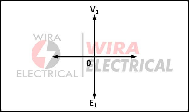
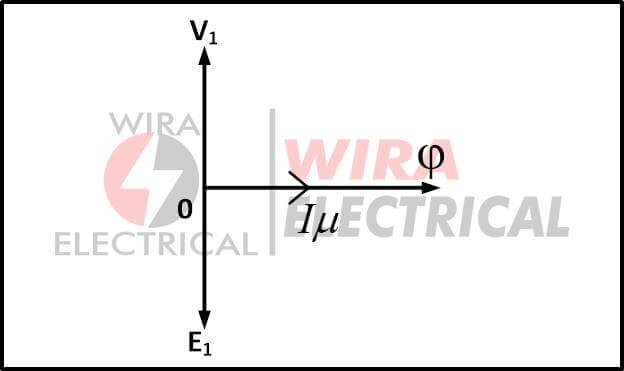
When an alternating source voltage V1 is given to the primary winding of that perfect transformer, a counter self emf E1 is induced in the primary winding, which is purely 180o out of phase with the supply voltage V1.

It draws current from the source to provide the necessary magnetizing flux for creating counter emf E1 across the primary winding.
Because the primary winding is completely inductive, the current lags behind the supply voltage by 90˚. This current is known as the transformer Iμ magnetizing current.

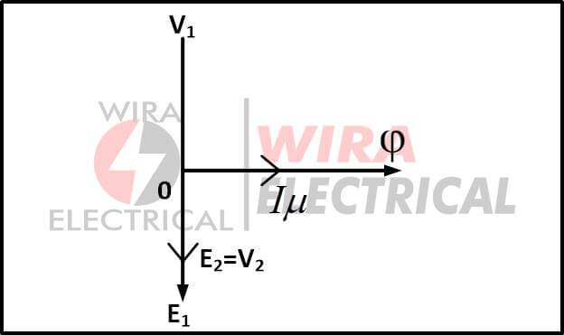
An alternating magnetizing flux Φ is produced by this alternating magnetizing current Iμ. Because the flux is proportional to the current that produces it, it will be in phase with the current.
This flux also connects the secondary winding to the transformer’s core.
As a result, another emf E2 is induced across the secondary winding, which is referred to as mutually induced emf in the diagram below.

Read also : RL and RC low pass filter circuit
Ideal Transformer Characteristics
After reading some explanation about an ideal transformer above, we can conclude that an ideal transformer has characteristics of:
- Zero winding resistance. The resistance of the primary and secondary windings of an ideal transformer is supposed to be zero. That is to say, both coils are inductive in nature.
- Infinite core permeability. The higher the permeability, the less (Magnetomotive Force) MMF is needed to establish flux. That is, if the permeability of the transformer core is large, less magnetizing current is required to magnetize the core.
- There is no leakage flux. Leakage flux is a type of magnetic flux that is unrelated to the secondary winding. The complete quantity of flux is supposed to be coupled with the secondary winding in an ideal transformer (that is, no leakage flux).
- 100% efficiency. A perfect transformer has no losses such as hysteresis loss, eddy current loss, and so on. As a result, the output power of an ideal transformer equals the input power perfectly. As a result, efficiency is 100 percent.
If an alternating voltage V1 is provided to the primary winding of an ideal transformer, the primary winding will generate a counter emf E1.
Due to the entirely inductive nature of the windings, the induced emf E1 will be exactly equal to the applied voltage but in 180 degree phase opposition.
The magnetic flux necessary is created by drawing current from the source. Because the primary winding is purely inductive, this current lags behind the induced emf E1 by 90˚.
This current is known as the transformer magnetizing current Iμ. An alternating magnetic flux Φ is produced by the magnetizing current I.
Mutual induction causes this flux Φ to be coupled to the secondary winding, causing emf E2 to be induced.
The mutually induced emf E2 is in phase with the induced emf E2.
E2 causes current I2 to flow in the circuit if a closed circuit is established at the secondary winding.
E1I1 = E2I2 for an ideal transformer.
Ideal Transformer Equation
The primary of the transformer is coupled to a voltage source v1.
![]()
Where V1 is the applied voltage’s RMS value. Let’s pretend there’s no load connected to the transformer secondary at first.
The coils have no resistance, therefore
![]()
The core is set up with a changing flux Φ, so that

The flux Φ produced fully links with the secondary coil since the leakage inductance is considered to be zero. The emf generated in the secondary can be provided by, for example.
![]()
Because the secondary coil’s resistance is also zero,

What we get from Equation (1) and equation (2),
![]()
In terms of voltage RMS value,
![]()
The transformation ratio, also known as the turns ratio, is the ratio between primary and secondary voltages and is symbolized by the letter ‘a.’

As a result, the voltage transformation ratio in an ideal transformer is the direct ratio of the number of primary and secondary turns.
Let us now imagine a secondary load Z2 that drains a sinusoidal current i2. A MMF is formed in the secondary as a result of the current flow, which opposes the flux.
![]()
Because F2 opposes mutual flux Φ, the primary drains a current i1, resulting in an MMF F1 that is provided by
![]()
Because the primary and secondary coils are connected by the same flux,
![]()
As a result of equations (4) and (5),

Taking a look at equations (3) and (6)

Hence,
![]()
For an ideal transformer, Equation.(8) implies that the input and secondary powers are always equal. When it comes to a transformer, however, this is not the case.
When it comes to RMS values,

The current is changed in the reverse ratio of the winding turns, according to the preceding equation.
Ideal Transformer Schematic Diagram
The schematic representation of an ideal transformer with the load Z2 connected to its secondary is shown below.

The polarity of the coil is shown by the dots in the diagram. Equation.(3) divided by Equation.(9),

Then

Thus,

The impedance on the secondary side will reflect in square of turns ratio times Z2 on the primary side, as shown by the preceding equation.
The turns ratio serves as the voltage transformation factor, the inverse of the turns ratio serves as the current transformation factor, and the square of the turns ratio serves as the impedance reference factor in an ideal transformer, while the power remains unchanged.
Ideal Transformer Advantages
The following are some of the benefits of the optimal transformer.
- There are no hysteresis, eddy, or copper losses.
- The twists of the coil fully determine the voltage and current ratios.
- There is no leakage of flux.
- It is independent of the frequency.
- Linearity that is perfect
- There is no stray capacitance or inductance.
As a result, an ideal transformer is a hypothetical transformer rather than a real transformer. This transformer is mostly used for educational purposes.