Electric Power Formula and Examples
If you’ve ever stared at a circuit and thought, “Why does this breaker keep tripping? Am I missing something obvious?” — that’s perfectly normal. Most people who work around electricity eventually hit a wall where the numbers feel a bit chaotic.
The funny thing is, once you understand the electric power formula, a lot of that noise settles down. You start recognizing how voltage, current, and load behavior connect. Things that felt random suddenly look… predictable. And honestly, that’s a great feeling.
Before we dive into formulas, let’s set a comfortable pace and go over what power actually represents.
What Electric Power Really Means
After learning about electrical voltage and electrical current, we still need to learn the last element of an electrical circuit. We still need to learn the electric power formula to solve all the electrical phenomena.
At its core, electric power is the rate at which electrical energy turns into something else — heat in a heater, torque in a motor, light in a bulb. Nothing mystical.
Here’s a picture you can keep in mind:
Voltage is the push, current is the flow, and power is how fast that flow can get work done.
And yes, the SI unit of electric power is the watt (W). Straightforward.
Why do people care so much about power? Honestly, because it’s the number that affects almost everything:
- whether your cable overheats
- whether a device draws too much current
- how much energy you’ll pay for
- how efficient your installation runs
So understanding it isn’t just “knowing more,” but working smarter.
The Electric Power Formula You’ll Use Everywhere
How much the power is absorbed by a circuit element depends on the capability of the said element and the energy supplied to the circuit. An 120 watt bulb compared to a 60 watt bulb will shine brighter. Not only how better it performs, our electrical bill is also calculated based on our power consumption
The more “watt” we use, the more bills we need to pay. We will use a DC circuit right now.
Based on this basic explanation, the circuit analysis of power and energy are not less important than voltage and current.
The relationship between power and energy to voltage and current can be stated as:
Power is the time rate of generating or absorbing energy, measured in watts (W)
The statement above can be expressed in mathematical equation as:
\( p \triangleq \frac{dw}{dt} \)
Where:
\( p \) = power, measured in watts (W)
\( w \) = energy, measured in joules (J)
\( t \) = time, measured in seconds (s)
In another way, electric power is the rate of electrical energy (w) transferred by an electrical circuit per unit of time (t).
Combining the equation above with the equation of voltage and equation of current, we will get the electric power formula:
\( p = \frac{dw}{dt}=\frac{dw}{dq}\cdot \frac{dq}{dt}= vi \)
From the equation above we can simply conclude that the electric power is the multiplication of electric voltage measured in volts ( \( V \) ) and the electric current measured in ampere (\( A \)). Electricity power here can be measured by \( V \times A \) or volt x ampere aside from watt.
The difference of volt-ampere and watt will be explained in detail in another lesson.
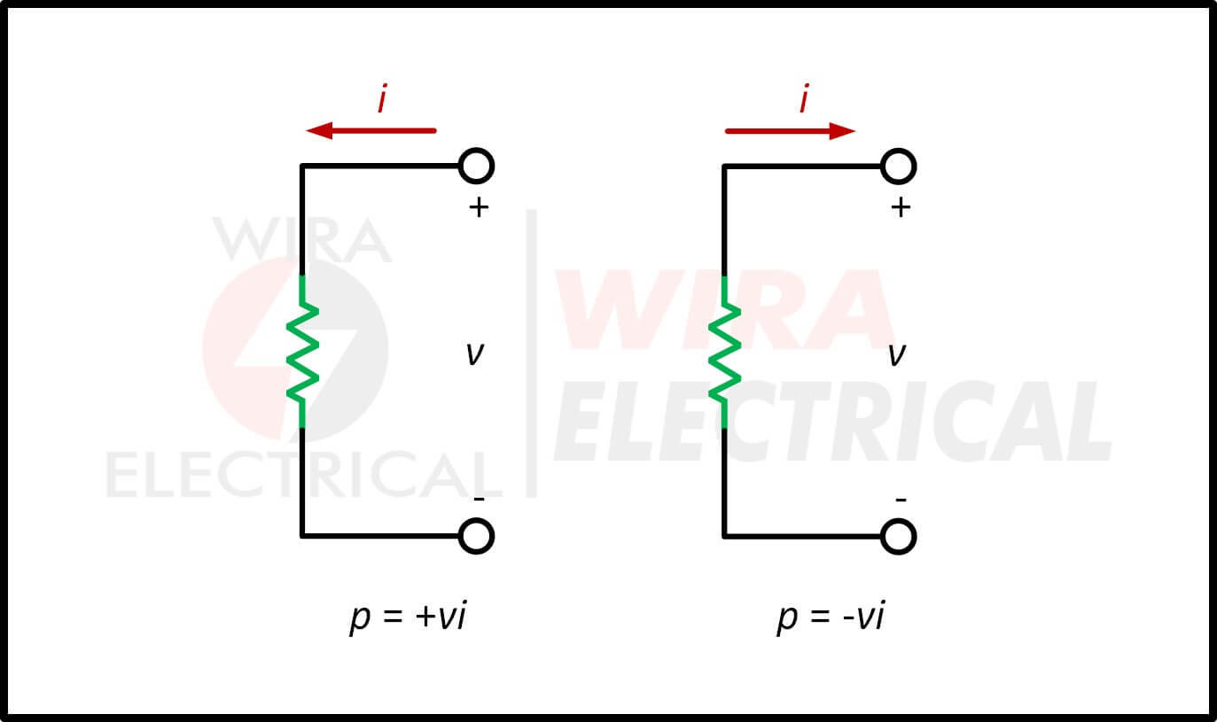
The equation above is called instantaneous power. If it has a positive (+) sign, it means the power is delivered to an element or the element is absorbing power. If it has negative (-) sign, it means the power is being supplied by the element. We can understand this after observing the illustration below.
Let’s begin with the classic:
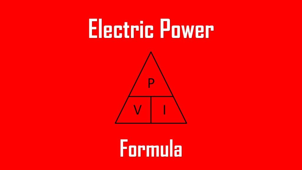
\( P = V \times I \)
Doesn’t look fancy, but it shows up in every installation drawing, every nameplate, and every troubleshooting session.
Variables:
\( P \) = power (W)
\( V \) = voltage (V)
\( I \)= current (A)
For DC systems, this is all you need.
But for AC, let’s bring Ohm’s Law into the picture.
Deriving Power From Ohm’s Law
Ohm’s Law:
\( V = I \times R \)
When you mix this with the power formula, two handy versions appear — the kind techs start depending on as they gain experience:
- \( P = I^2 R \)
Shows how power skyrockets with current.
A slight bump in current? Big jump in heat.
- \( P = V^2 / R \)
Useful when you know voltage and resistance.
These aren’t “school only” formulas — they’re practical, especially when diagnosing why components run hot.
Let’s Separate DC, Single-Phase AC, and Three-Phase Power
Many guides mix them, but clarity helps more.
- Power in a DC Circuit
Easy:
\( P = V \times I \)
Example:
A 12 V supply feeding 5 A → 60 W.
It’s clean, consistent, and predictable.
- Single-Phase AC Power
AC adds one twist: power factor (pf).
\( P = V \times I \times pf \)
Power factor tells you how effectively current creates real work.
Standards like IEC 60364 and IEEE 1459 formalize it, but you don’t need the full textbook to use it correctly.
- Three-Phase Power
This is the backbone of commercial and industrial systems:
\( P = \sqrt{3} \times V_L \times I_L \times pf \)
Line voltage, not phase voltage — easy to mix up if you’re in a hurry.
Power Absorbed and Delivered
There is another easy way to determine the sign of power, by determining the direction of current and voltage first.
Observe the illustration below.
The illustration above shows us how to get a positive sign. This is widely known as the passive sign convention.
In the illustration above, the current is entering the positive polarity of voltage, it makes the power p = +vi or p > 0 implies that the element is absorbing power and the absorbed power formula is p = vi.
Opposite of that, observe the illustration below.
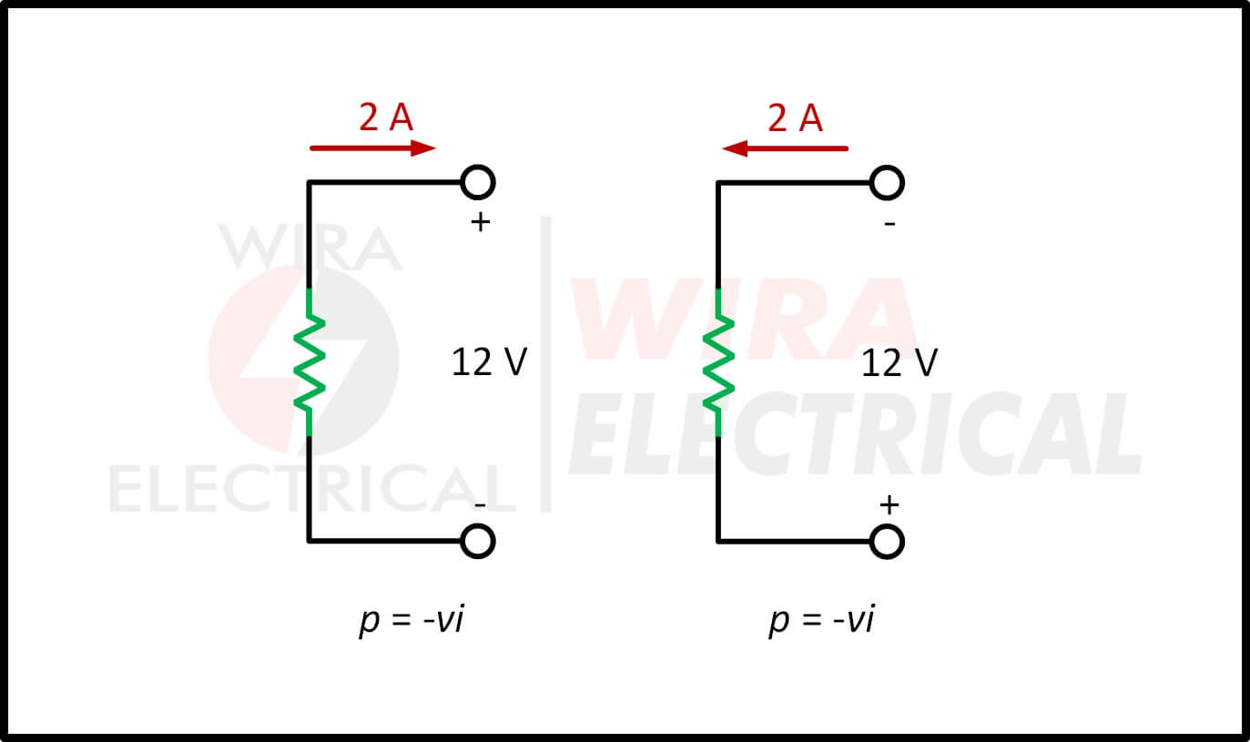
The illustration above tells us that the element is supplying power since the current is leaving the element at the positive polarity (think of it as a battery, it shares the same illustration).
In the illustration above, the current is leaving the positive polarity of voltage, it makes the power p = -vi or p < 0 implies that the element is delivering power and the delivered power formula is p = -vi.
Passive sign convention is achieved when the current enters through the positive terminal of an element and p = +vi, if the current enters the negative terminal, p = -vi
A Practical Step-by-Step Example
Let’s walk through something typical.
You have a 230 V single-phase air compressor pulling 8 A with a pf of 0.85.
Step 1
\( P = V \times I \times pf \)
Step 2
\( P = 230 \times 8 \times 0.85 \)
Step 3
\( P \approx 1,564 W \)
Step 4: Real-world implications
According to IEC 60364:
- A 1.56 kW load normally pairs with a 10–16 A breaker
- Cable choice depends on length, installation method, and temperature
This is the stuff electricians calculate dozens of times a week.
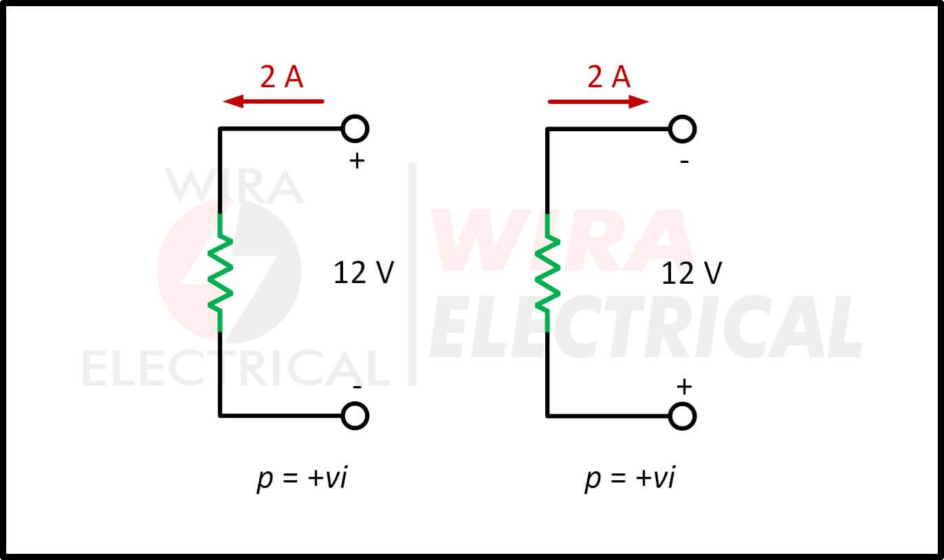
For all the illustrations shown above, we can conclude that:
(+) power absorbed is equal to (-) power supplied
Because absorbing -12W power is equal to supplying +12W power.
This is another approach to prove that the law of conservation of energy will always be obeyed by any electrical circuit. The mathematical equation itself is:
\( \sum p = 0 \)
From the equation above it is clear that the total power supplied must balance the total power absorbed.
When calculating energy in a specific period of time, we can use:
\( w = \int_{t_0}^{t} p \quad dt = \int_{t_0}^{t} vi \quad dt \)
The electric power utility measure their energy in watt-hours (Wh) where:
1 Wh = 3.600 Joules
Quick Real-World Examples
For better understanding, let us review some examples below:
1. An energy source generates a constant current of 2 A for 10s to turn on a light bulb. If 2,3 kJ is used to produce light and heat, how much voltage drop for the bulb?
Answer:
The total charges is
\( \Delta q = i \Delta t = 2 \times 10 = 20C \)
The voltage drop is
\( v = \frac{\Delta w}{\Delta q} = \frac{2.3 \times 10^3}{20} = 115V \)
2. Calculate the power delivered to an element at t = 3 ms if the current is entering at the positive terminal.
The current is
\( i = 5 \cos 60 \pi t A \)
The voltage is
(a) v = 3i, and
(b) v = 3 di/dt
Answer:
Let’s start with voltage(a) first.
\( v = 3i = 15 \cos 60 \pi t \)
Hence, the power is
\( p = vi = 75 \cos^2 60 \pi t \quad W\)
At t = 3 ms,
\( p = 75 \cos^2 (60 \pi \times 3 \times 10^{-3}) = 53,48 W \)
Now we will proceed to voltage(b)
$$
\begin{aligned}
v &= 3\frac{di}{dt} = -3 (-60\pi)5 \sin 60 \pi t \\
&= -900 \pi \sin 60 \pi t \quad V
\end{aligned}
$$
Hence, the power is
\( p = vi = -4500 \pi \sin 60 \pi t \cos 60 \pi t \quad W \)
At t = 3 ms,
$$
\begin{aligned}
p &= -4500 \pi \sin 0,18 \pi \cos 0,18\pi \quad W \\
&= -14137,167 \sin 32,4^{\circ} \cos 32,4^{\circ}\\
&= -6,396 kW
\end{aligned}
$$
3. Imagine we have a simple electrical circuit with a resistor and a voltage source. The power measured across the resistor is 10 watt while the voltage source is 5 volts. Calculate the current flowing in the circuit and the resistance of the resistor.
Answer:
We can easily solve this with
$$
\begin{aligned}
p &= vi \\
10 &= 5i \\
i &= 2 A
\end{aligned}
$$
Since we have the voltage and the current, we can easily find the resistance with Ohm’s Law. But here we will involve the power.
Since,
$$
\begin{aligned}
v &= iR \\
p &= i^2 R \\
10 &= 2^2 R \\
R &= 2,5 \Omega
\end{aligned}
$$
Pros, Cons, and Practical Notes
Aspect | Upside | Downside |
High power | Handles bigger loads | Needs thicker cables |
Low power | Cheaper components | May struggle with heavy tasks |
AC power | Easy voltage transformation | Power factor considerations |
DC power | Perfect for electronics | Poor long-distance performance |
No surprises — just everyday engineering trade-offs.
Common Mistakes (And How to Avoid Them)
You might recognize a few of these:
- ❌ Forgetting power factor on AC loads
- ❌ Mixing kW and kWh
- ❌ Using DC formulas for AC
- ❌ Ignoring efficiency percentages
- ❌ Trusting nameplate current blindly
Fix these, and most power-related errors vanish.
Best Practices for Accurate Power Work
Some habits that help in the long run:
✔ Use the correct formula for the circuit type
✔ Refer to IEC/IEEE standards when sizing
✔ Consider efficiency (nothing is 100%)
✔ Double-check units
✔ Measure actual current when possible
✔ Leave headroom in design
Honestly, these small habits make designs safer and easier to maintain.
Conclusion
If you’re still here, that already says something: you’re the type who wants to understand things properly, not just “good enough.”
The electric power formula seems simple, but it’s the lens through which you interpret almost every load, circuit, and device. Once the relationship between voltage, current, resistance, and power factor clicks, everything from troubleshooting to planning starts feeling more coherent.
Thanks for sticking through. Curiosity like this is basically an engineer’s superpower.
FAQ
1. What is electric power in simple words?
It’s how fast electricity turns into something useful.
2. What is the SI unit of power?
Watt (W).
3. What formula do I use?
Start with P = V × I.
4. Are power and energy the same?
No. Power is instant; energy accumulates.
5. How do I calculate power consumption?
Multiply voltage and current.
6. How do AC circuits differ?
They include the power factor.
References
- IEC 60038
- IEC 60364
- IEC 60034
- IEEE Std 141
- Alexander & Sadiku
- Fitzgerald – Electric Machinery