Current Division Rule: A Practical Walkthrough From an Engineer Who’s Been There
If you’ve worked with electrical circuits long enough, you’ve probably hit that moment where a parallel network doesn’t behave the way you expected. Maybe a resistor got warmer than its neighbor, or a small current-sensing line picked up more load than you thought it would. Don’t worry — most of us have been confused by current paths at some point.
That’s exactly where the current division rule earns its keep. It’s simple enough to teach in a first-year circuits class but powerful enough to show up in real engineering work every day. Whether you’re troubleshooting a distribution panel or just brushing up for a project, understanding how current splits makes your job far easier.
Let’s walk through the idea from the ground up — starting with the basics, then drifting into the calculations, and finally touching real applications where this rule genuinely matters.
What Is the Current Division Rule?
Current division rule is implemented in a current divider circuit. This circuit uses parallel connected resistors rather than series connected resistors like what we have learnt in a voltage divider circuit.
If the voltage divider circuit has equal current through each resistor, the current divider circuit has equal voltage across each resistor.
In the simplest form, the current division rule explains how total current divides among parallel resistors. Since each branch sees the same voltage, the distribution depends entirely on each branch’s resistance.
Lower resistance… more current
Higher resistance… less current.
Pretty intuitive once you see it that way.
Standards like IEC 60364, IEC 60287, and NEC Article 310 lean heavily on this principle when discussing parallel conductors and load-sharing. And if you’re into IEEE references, the Red Book (IEEE 141) mentions parallel feeder behavior that’s basically a real-world extension of the same math.
A Quick Mental Picture Before the Math
Here’s a small analogy that often helps new engineers:
Imagine two pipes in parallel. One pipe is wider, the other narrower. If you force water through both at the same pressure, more water flows through the wider path.
Current does the same thing.
If both branches are tied to the same node pair — same voltage — then electrons don’t “choose” a path; they simply flow according to the resistance.
Once this idea lands, the formula becomes almost obvious.
The Main Formula (Current Division Rule)
Here’s the expression for two resistors in parallel. Total current \( I_T \) enters the junction and splits into \( I_1 \) and \( I_2 \) across \( R_1 \) and \( R_2 \).
\( I_1 = I_T \cdot \frac{R_2}{R_1 + R2} \)
And the other branch:
\( I_2 = I_T \cdot \frac{R_1}{R_1 + R2} \)
Many learners expect \( R_1 \) to appear in the numerator of the expression for \( I_1 \), but the opposite resistance shows up instead. It’s normal to question this the first time — almost everyone does.
A quick reminder: the branch with lower resistance gets the higher current, and the formula reflects that neatly.
Current divider rule follows Kirchhoff’s Current Law where the sum of all currents entering a node is equal to the sum of all currents leaving the same node. Each current entering and leaving a node is determined by the resistance of each branch connected to that node.
Observe the DC circuit below.
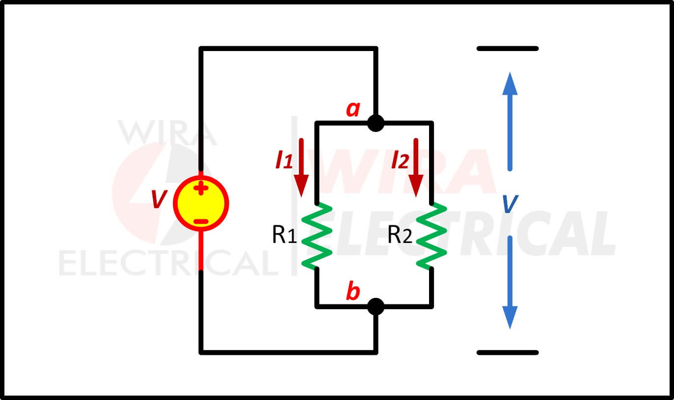
From the node a and b, the Kirchhoff’s Current Law states that:
The algebraic sum of all currents entering a node is equal to the algebraic sum of all current leaving a node.
Or in other words:
The algebraic sum of all currents entering and leaving a node equals zero.
The current entering node a is equal to the current leaving node b. Between node a and b, the current is divided into two branches, \( I_1 \) and \( I_2 \) with their resistance \( R_1 \) and \( R_2 \) respectively with V as the voltage drops across the both resistances (\( R_1 \) and \( R_2 \)).
In a parallel circuit, the voltage drop across each resistor connected in a parallel is equal to each other (\( V_1 = V_2 = V_3 \) …). In a series circuit, the current flowing through each resistor connected in a series is equal to each other (\( I_1 = I_2 = I_3 \)).
Current Divider Rule Derivation (Step-by-Step)
Engineers like to know where formulas come from. So let’s unpack it, but without turning this into a textbook lecture.
From the Ohm’s Law we already know that
\( V = I \times R \)
Use this to calculate the current for each branch in the circuit
\( I_1 = \frac{V}{R_1}, I_2 = \frac{V}{R_2} \)
The total resistance in that parallel circuit is
\( R = \frac{R_1 R_2}{R_1 + R_2} \)
Substituting these two gives us
\( I = \frac{V(R_1 + R_2}{R_1 R_2} \)
Across parallel resistors, voltage is equal:
\( V = I_1 R_1 = I_2 R_2 \)
We also know from KCL:
\( I = I_1 + I_2 \)
From the equal-voltage condition:
\( I_2 = I_1 \cdot \frac{R_1}{R_2} \)
Now plug that into KCL:
\( I = I_1 + I_1 \cdot \frac{R_1}{R_2} \)
Factor \( I_1 \):
\( I = I_1 (1 + \frac{R_1}{R_2}) \)
And solve:
\( I_1 = I \cdot (\frac{R_2}{R_1 + R_2}) \)
Nothing fancy — just Ohm, Kirchhoff, and a little algebra.
How to Calculate Branch Current Step-by-Step
Use the circuit example above to understand how we use the current division formula.
You have:
\( R_1 = 8 \Omega, R_2 = 4 \Omega \)
Total current, \( I = 12 A \)
1. Write the formula:
\( I_1 = I \cdot \frac{R_2}{R_1 + R_2} \)
2. Substitute:
\( I_1 = 12 \cdot \frac{4}{8 + 4} \)
3. Solve:
\( I_1 = 12 \cdot \frac{4}{12} = 4A \)
4. Then:
\( I_2 = I – I_1 = 12 – 4 = 8A \)
If you checked the resistors afterward, you’d notice the 4-ohm branch heating more — and that matches the math perfectly.
It will be quite different with a circuit consisting of three or more resistors connected in parallel.
The equivalent resistance will be divided by the resistance of a branch where the desired current flows through. Mathematically, the current divider rule for 3 resistors is the total current multiplied by the fraction of equivalent resistance to the respective resistance of a branch.
Using the Current Divider in AC Circuits
Some engineers hesitate when switching to AC analysis. But the truth is, the current divider rule works the same way — you just use impedance instead of resistance.
For two parallel impedances \( Z_1 \) and \( Z_2 \) :
\( I_1 = I_T \cdot \frac{Z_2}{Z_1 + Z_2} \)
This matters in:
- RLC filters
- Power-factor correction banks
- Instrument transformer loading
- High-frequency electronics
- Resonant networks
Just be mindful: impedances are complex numbers. The magnitudes and angles matter.
Current Divider Rule Examples
To make it easier to understand, we will review a few examples below.
- Observe the simple circuit below to solve how the current divider circuit with two resistors is solved.
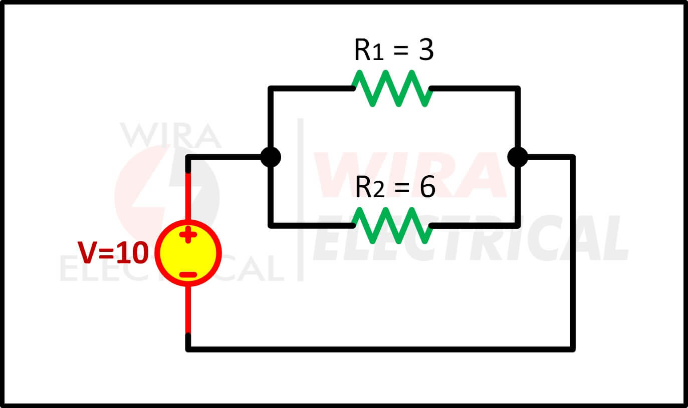
The equivalent resistance is
$$
\begin{align*}
R&=\frac{R_{1}R_{2}}{R_{1}+R_{2}}\\
&=\frac{3\times6}{3+6}\\
&=2 \Omega
\end{align*}
$$
The total current is
$$
\begin{align*}
I&=\frac{V}{R}\\
&=\frac{10}{2}\\
&=5A
\end{align*}
$$
The current \( I_1 \) is
$$
\begin{align*}
I_{1}&=I\frac{R_{2}}{R_{1}+R_{2}}\\
&=\frac{5\times6}{3+6}\\
&=\frac{10}{3}A
\end{align*}
$$
The current \( I_2 \) is
$$
\begin{align*}
I_{2}&=I\frac{R_{1}}{R_{1}+R_{2}}\\
&=\frac{5\times3}{3+6}\\
&=\frac{5}{3}A
\end{align*}
$$
This clarifies what Kirchhoff’s Current Law statement
$$
\begin{align*}
I&=I_{1}+I_{2}\\
5A&=\frac{10}{3}+\frac{5}{3}\\
5A&=5A
\end{align*}
$$
- Now we will try to solve a current divider rule for 3 resistors.
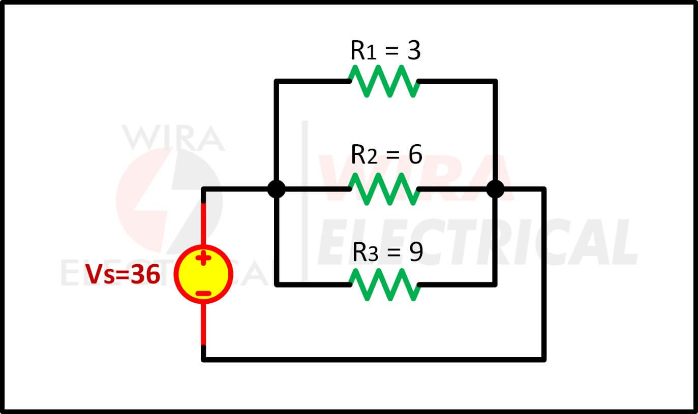
The equivalent resistance is
$$
\begin{align*}
\frac{1}{R}&=\frac{1}{R_{1}}+\frac{1}{R_{2}}+\frac{1}{R_{3}}\\
&=\frac{1}{3}+\frac{1}{6}+\frac{1}{9}\\
&=\frac{12}{36}+\frac{6}{36}+\frac{4}{36}\\
\frac{1}{R}&=\frac{22}{36}\\
R&=\frac{36}{22}=\frac{18}{11}\Omega
\end{align*}
$$
The total current is
$$
\begin{align*}
I&=\frac{V_{S}}{R}\\
&=\frac{36}{18/11}\\
&=22A
\end{align*}
$$
The voltage drop across each resistor is
$$
\begin{align*}
V&=I\times R\\
&=22\times\frac{18}{11}\\
&=36V
\end{align*}
$$
The equivalent circuit is
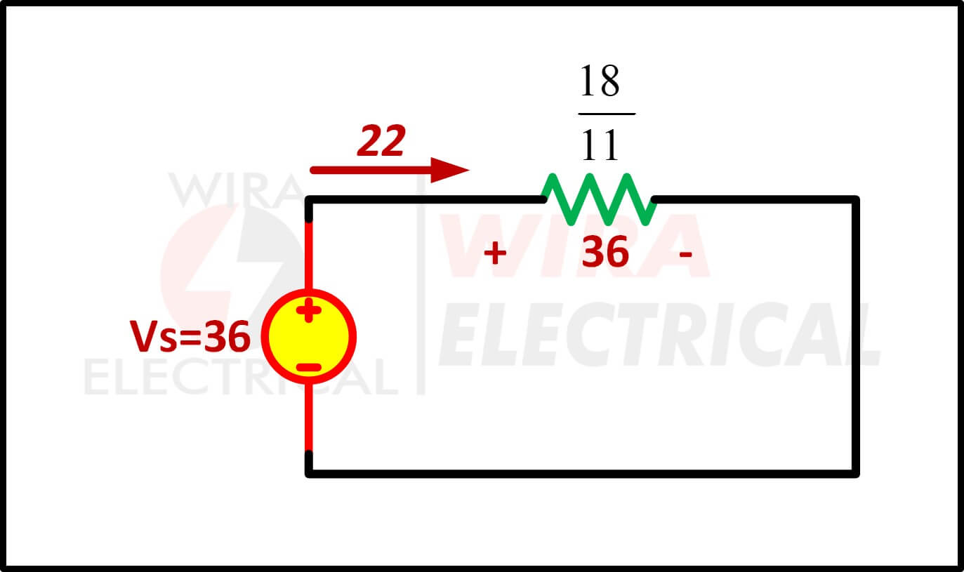
Since the parallel circuit has equal voltage drop across each resistor connected in parallel, then
\( V=V_{1}=V_{2}=V_{3}=36 \)
The current flowing through each branch are
$$
\begin{align*}
I_{1}&=\frac{V}{R_{1}}=\frac{36}{3}=12A\\
I_{2}&=\frac{V}{R_{2}}=\frac{36}{6}=6A\\
I_{3}&=\frac{V}{R_{3}}=\frac{36}{9}=4A
\end{align*}
$$
This is a common method to find the current flowing in each branch. But there is a shortcut method where we directly use the equivalent formula.
We still need to calculate the total current, from the equation above we know that the total current (\( I \)) is 22 A.
We will use equations above to find the \( I_1 \), \( I_2 \), and \( I_3 \).
$$
\begin{align*}
I_{1}&=I\times\frac{R}{R_{1}}=22\times\frac{18/11}{3}=12A\\
I_{2}&=I\times\frac{R}{R_{2}}=22\times\frac{18/11}{6}=6A\\
I_{3}&=I\times\frac{R}{R_{3}}=22\times\frac{18/11}{9}=4A
\end{align*}
$$
Where Engineers Actually Use the Current Divider Rule
Here are a few real places where this rule comes up — beyond homework problems.
1. LED Loads
Parallel LED strings don’t share current evenly. Designers add small balancing resistors to control current division.
2. Parallel Feeders in Electrical Installations
Both the NEC and various IEC standards warn that parallel cables rarely share current equally due to differences in impedance. Engineers use current division concepts to estimate worst-case imbalance.
3. Measurement Circuits
Shunt resistors, Hall sensors, and current-sense amps often rely on predictable current paths. If division is off, the measurement is off.
4. Battery Banks
Parallel lithium cells can drift in internal resistance, causing uneven current draw — sometimes dangerously uneven.
5. Power Electronics
MOSFETs and diodes placed in parallel need proper balancing, often through small series resistors or source resistances.
Once you start looking for it, the current division shows up everywhere.
Advantages and Disadvantages at a Glance
Category | Advantages | Disadvantages |
Ease of Use | Quick way to estimate branch currents | Misapplied when voltage across branches differs |
Accuracy | Works well with matched components | Sensitive to resistor tolerance |
Flexibility | Works for DC and AC (with impedance) | Complex values make AC math heavier |
Troubleshooting | Helps identify unbalanced loads | Real wires have temperature effects and parasitics |
Common Mistakes When Using the Current Division Rule
You’ll run into the same few pitfalls over and over — whether you’re new or experienced.
1. Using It on Non-Parallel Circuits
Series circuits need the voltage divider rule, not this one.
2. Ignoring Component Tolerance
A 5% difference can shift currents more than people expect.
3. Forgetting Temperature Effects
Conductors heat up, resistances rise, current distribution changes.
(IEC 60287 has the details.)
4. Applying It Blindly in AC Without Impedance
Resistors? Easy.
Inductors and capacitors? Not unless you switch to \( Z \).
5. Assuming Equal Sharing in Power Paths
Parallel feeders, parallel MOSFETs, and LED strings rarely share nicely.
Once you’ve seen a few circuits behave unexpectedly, these become second nature.
Tips and Best Practices From the Field
- Double-check that the circuit is truly parallel — a surprising number aren’t.
- Use matched components when equal sharing matters.
- For AC analysis, stick to full impedance values, not resistance alone.
- Add ballast resistors or small equalizing resistances for power circuits.
- When in doubt, use a quick SPICE simulation as a sanity check.
A few minutes running a model can save hours of troubleshooting.
Conclusion
The current division rule may look like a small piece of circuit theory, but it consistently earns its spot in every engineer’s toolbox. It helps you predict real currents, understand unexpected heating, and make decisions that align with practical standards like IEC, IEEE, and NEC guidelines.
If you’ve followed the explanations and formulas above, you’re already thinking more like a practicing engineer than a textbook reader. The next time you meet a branching circuit on the job, try evaluating it with the rule — you’ll likely spot issues or insights you would’ve missed otherwise.
FAQ
1. Does the rule work with inductors or capacitors?
Yes. Replace resistance with impedance and you’re good.
2. How much do resistor tolerances affect current division?
Quite a bit. Even a few percent can skew the currents noticeably.
3. Can I use the rule for three or more branches?
Absolutely — the conductance-based formula handles any number.
4. Does lower resistance always draw more current?
In pure DC parallel circuits, yes.
5. Does this apply to fault current studies?
Only partially. For real faults, follow IEC 60909 or IEEE 551.
References
- IEC 60364 — Low-Voltage Electrical Installations
- IEC 60287 — Cable Current-Carrying Capacity
- NEC Article 310
- IEEE Std 141
- Alexander & Sadiku, Fundamentals of Electric Circuits
- Boylestad, Introductory Circuit Analysis


I like it