Understanding Branches, Nodes, and Loops in Electric Circuits — A Practical Engineer’s Guide
If you’ve ever tried tracing wires across a circuit diagram and felt like you were following a maze, you’re not alone. Whether you’re building a small sensor board or analyzing a three-phase industrial system, understanding branches, nodes, and loops is where organized circuit analysis really begins. Once these basic elements click, everything else — Ohm’s law, Kirchhoff’s laws, even mesh and nodal analysis — suddenly makes sense.
And here’s the good news: learning them doesn’t require fancy math at first. It just takes a bit of visualization, a few clear definitions, and the patience to connect the dots — literally. Let’s walk through it together.
Why These Concepts Matter
Every circuit, no matter how simple or complex, can be broken into connections (nodes), paths (branches), and closed routes (loops). Engineers use this framework to organize current flow, calculate voltages, and apply mathematical tools such as Kirchhoff’s Current Law (KCL) and Kirchhoff’s Voltage Law (KVL).
Without this structure, a circuit schematic is just a tangle of lines. But once you identify its nodes and loops, it becomes a logical network. Mastering this will help you:
- Diagnose voltage drops and current paths faster.
- Simplify complex networks into solvable pieces.
- Verify circuit integrity using IEC 60617 or IEEE 91-1984 drawing standards.
- Communicate clearly with other engineers — because the language of nodes and loops is universal.
So, let’s start from the ground up.
What Is a Node in an Electrical Circuit?
Think of a node as a junction — any point where two or more circuit elements connect. If current can split, merge, or change direction at that spot, you’ve found a node.
Formal Definition
Define node in electrical circuit:
A node is the point where two or more branches are connected together.
A node is represented by a dot in an electric circuit. Understand that if a short circuit (a plain conducting wire) is connected to two nodes, these two nodes form a single node. Observe the example circuit below:
Visualizing Nodes
Imagine a simple circuit: a voltage source connected to two resistors in parallel. The wire joining the positive terminal of the source and both resistors is one node. The wire connecting their other ends to the negative terminal is another node. Even if you draw them with bends or extended lines, they still count as single electrical points because their potential is identical.
In practice, nodes are labeled as \( N_1, N_2 \) , etc., or with letter tags (a, b, c…). You can choose any node as your reference — typically the one tied to ground.

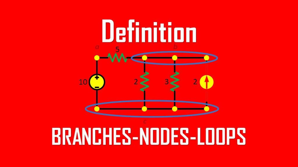
In the circuit above we can list three nodes that exist inside it: nodes a, b, and c. The three nodes connected to a single wire form a single node b.
Just as node b, we can also treat node c as the same. After understand a bit about node, we can redraw the circuit above into circuit below:

Don’t worry, both circuits are identical.
What Is a Branch in a Circuit?
A branch is simply a path that connects two nodes and contains one or more circuit elements. Each branch carries a single current value, although the voltage across it can vary depending on what’s inside.
Formal Definition
A branch represents a single path for current flow between two nodes and includes the components connected along that path.
In our parallel-resistor example, each resistor plus the connecting wires forms one branch. The voltage across all branches that share the same two nodes is identical, but the current in each may differ based on resistance.
Branches are counted when performing circuit topology checks. For a network with N nodes and B branches, you’ll often verify that:
\( L = B – N + 1 \)
where L is the number of independent loops (we’ll get to that soon).
Define branch in electrical circuit
A branch is a circuit element such as voltage or current source or a resistor, capacitor, inductor.
For a better understanding, you can observe the circuit example below:

The circuit above we can see that we have five branches:
- The 10V voltage source
- The 5Ω resistor
- The 2Ω resistor
- The 3Ω resistor
- The 2A current source
What Is a Loop in a Circuit?
Now for the fun part — loops. A loop is any closed conducting path through which current can circulate. When you trace a loop, you end up exactly where you started without lifting your pencil.
Formal Definition
A loop is a closed path in a circuit that begins and ends at the same node, containing no other node more than once.
Every electrical network contains many loops, but only some are independent. Independent loops are those that include at least one branch not contained in any other loop. Identifying these lets you apply Kirchhoff’s Voltage Law efficiently — you only need equations for the independent loops.
Analogy
If nodes are intersections and branches are roads, then a loop is a round-trip route that brings you back to the same intersection. Some routes may overlap (shared branches), but each unique round-trip adds new information to the map.
We can call a loop independent if the loop contains at least one branch which is not a part of another independent loop.
Define loop in electrical circuit:
A loop is a closed path inside an electric circuit.
Observe the circuit below:

It is a common thing to find an independent loop where it doesn’t contain such a branch. In the circuit above we list the independent loo
- The path abca with 2Ω resistor.
- The path bcb with 3Ω resistor and current source.
- The path with 3Ω resistor and 2Ω resistor in parallel.
Mathematical Relations Between Nodes, Branches, and Loops
Topology gives us a neat relationship that keeps circuit analysis organized. For any connected planar network:
\( L = B – N + 1 \)
where
- L = number of independent loops
- B = number of branches
- N = number of nodes
This formula, derived from graph theory, is widely used in electrical engineering. For example, IEC 61082 (Preparation of Documents Used in Electrotechnology) and IEEE 315 both rely on similar topological consistency rules to check whether a circuit diagram is properly connected.
Example:
A circuit has 5 nodes and 7 branches.
Then
\( L = 7 – 5 + 1 = 3 \)
So, the circuit contains three independent loops — meaning you need three independent KVL equations to fully describe its voltages.
Why Independent Loops Matter
Independent loops provide non-redundant equations for voltage analysis. Dependent loops, by contrast, don’t add new information because their voltages can be derived from others. This efficiency is what makes mesh or loop analysis practical for large networks.
When combined with KCL at selected nodes, independent loops create a complete solvable system. Computer-aided tools like SPICE and MATLAB use these relationships internally to form nodal matrices and loop matrices during simulation.
How Kirchhoff’s Laws Tie It All Together
Once you’ve marked out your circuit’s branches, nodes, and loops, you can finally bring the analysis to life with Kirchhoff’s Laws. These two simple but powerful rules describe how voltage and current behave in every electrical network.
Kirchhoff’s Current Law (KCL)
KCL says that the total current entering a node must equal the total current leaving it.
Mathematically:
\( \sum I_{in} = \sum I_{out} \)
That’s really just a formal way of saying charge can’t pile up at a junction. The electrons that enter a node have to leave somewhere.
If three wires meet at a node and two of them carry 2 A each toward it, the third wire must carry 4 A away — no exceptions. Whether it’s a breadboard circuit or a 33 kV switchboard, this rule still applies.
You might think this law is obvious, but in real-world troubleshooting, it’s what tells you whether something’s wrong. If current doesn’t balance at a node, you’ve got an open circuit, a hidden load, or a measurement error.
Kirchhoff’s Voltage Law (KVL)
KVL works the same magic but around loops. It states that the algebraic sum of voltages in any closed path is zero.
\( \sum V = 0 \)
Why? Because electrical energy is conserved. Whatever energy a charge gains from sources must be lost through resistors, capacitors, or other elements by the time it returns to its starting point.
Let’s say you have a loop with a 12 V battery and two resistors in series. If the first resistor drops 7 V, the second must drop 5 V. Add them up — you’re back to zero.
KVL is what keeps your mesh equations balanced when performing loop analysis. Without it, a circuit simulation wouldn’t converge; the energy bookkeeping simply wouldn’t work out.
Putting It All Together: Node and Mesh Analysis
After understanding KCL and KVL, you can apply two standard methods that make use of these rules: nodal analysis and mesh analysis.
Each has its sweet spot, and once you know when to use which, circuit-solving becomes almost intuitive.
Nodal Analysis
Nodal analysis uses KCL at the nodes to find node voltages. Here’s the general workflow:
- Choose a reference node (ground).
- Label all remaining node voltages relative to that reference.
- Apply KCL to each non-reference node.
- Express each branch current in terms of the node voltages using Ohm’s law.
- Solve the resulting simultaneous equations.
It’s ideal for circuits with many parallel connections or when current sources dominate. Simulation tools like SPICE use a modified version called Modified Nodal Analysis (MNA), which also accounts for voltage sources and dependent elements.
Mesh (Loop) Analysis
Mesh analysis, on the other hand, applies KVL to independent loops to find loop currents. Steps are just as systematic:
- Identify independent loops (using \(L = B – N +1 \) ).
- Assign a loop current to each, usually clockwise.
- Apply KVL to every loop.
- Express voltages in terms of these loop currents and resistances.
- Solve the simultaneous equations.
This method shines in planar circuits with fewer loops than nodes — think ladder networks, amplifiers, or small-signal transistor circuits.
Real-World Applications of Nodes, Branches, and Loops
Now that you can recognize nodes, branches, and loops on paper, it’s time to see where these ideas actually show up. Because theory is great — but what makes it stick is seeing it come alive in real systems.
1. Residential and Building Wiring
In home electrical layouts, each circuit breaker and its connected loads form individual branches.
The main distribution bar becomes a key node, where incoming supply splits into multiple branch circuits.
When electricians calculate load balance or voltage drop, they’re unknowingly applying node-branch logic — deciding which paths share potential and how much current flows through each.
2. Industrial Power Systems
Large plants use looped distribution networks for reliability. If one feeder fails, power can reroute through another branch of the loop.
In such systems, engineers apply Kirchhoff’s laws when setting relay coordination and verifying current balance across CTs and busbars. Standards like IEC 60909 and IEEE C37 still rely on the same topological logic you learned from simple DC circuits.
3. Electronics and PCB Design
On printed circuit boards, a node may represent a copper net connecting several IC pins.
Branches are the individual traces linking them, and loops appear in return paths — especially in analog or high-frequency designs.
A poorly designed loop can act as an antenna or introduce noise. That’s why PCB designers talk about “minimizing loop area” — it reduces electromagnetic interference (EMI).
So yes, even in GHz-range circuits, the humble loop still rules the game.
4. Measurement and Troubleshooting
When troubleshooting, experienced engineers automatically think in nodes and loops.
Say a sensor signal isn’t reaching the controller — you mentally follow the branch from the transmitter node, through connectors, and back to the control node. Somewhere along that branch, continuity is lost.
Current doesn’t lie. If it doesn’t add up at a node, something’s wrong — and KCL becomes your best friend.
Best Practices When Working with Circuit Topology
Here are a few habits that make real-world analysis easier — and can save hours later:
- Label everything early.
Use consistent node and branch names. Tools like AutoCAD Electrical and EPLAN follow IEC 81346 for this reason. - Choose the right reference node.
Ground isn’t always the physical earth. Pick the most stable potential as your zero reference. - Double-check connectivity.
Many circuit errors trace back to missing node links. A continuity test or netlist verification can catch these before power-up. - Keep your schematic planar.
Overlapping wires cause confusion. Redraw complex networks so loops and crossings are easy to trace. - Use KCL to sanity-check measurements.
If the sum of currents at a node doesn’t balance, you’ve either miswired or misread. - Visualize energy flow.
When you picture voltage sources giving energy and resistors consuming it, KVL becomes intuitive — not just algebra.
Common Mistakes Beginners Make
Even seasoned engineers occasionally stumble over these:
- Counting multiple wires at the same potential as different nodes.
Remember: identical potential = one node. - Over-identifying loops.
Many loops may exist, but only some are independent. Extra equations only add redundancy. - Ignoring polarity in KVL equations.
Consistent sign convention prevents confusion — clockwise voltage drops are negative if you define loop current clockwise. - Forgetting practical resistances.
Wires, connectors, and even measurement leads introduce small but real voltage drops. They affect KVL balance in sensitive circuits.
Nodes, Branches, and Loops Examples
For better understanding let us review the examples below:
Observe the circuit below and count the number of branches and nodes. Also identify which parts are in series or parallel.

The circuit above has four element, thus it has four branches:
- 10V voltage source,
- 5Ω resistor,
- 6Ω resistor, and
- 2A current source
It has three nodes as shown the circuit below:

The series connection is formed from a 10V voltage source and 5Ω resistor. The parallel connection is formed from a 6Ω resistor and 2A current source connected to nodes 2 and 3.
Frequently Asked Questions
Q1: Are nodes and junctions the same thing?
Pretty much, yes. A node is any electrical junction where elements share the same potential. Multiple physical terminals may still belong to one logical node if they’re directly connected.
Q2: What’s the difference between a loop and a mesh?
Every mesh is a loop, but not every loop is a mesh. A mesh is a loop that contains no other loops inside it — the smallest possible closed path.
Q3: Can I apply these ideas to AC or complex circuits?
Absolutely. The concepts don’t change. You’ll just express voltages and currents as phasors instead of real numbers.
Q4: How can I check if my schematic follows KCL and KVL?
You can simulate it using SPICE, or even do a quick manual check. Sum all currents at each node (KCL) and voltages around each loop (KVL). If they don’t balance, something’s missing or mis-labeled.
Q5: Why does counting matter in large power networks?
Because it ensures the system model is mathematically complete. Utilities use topological data to validate network integrity before running load-flow or fault studies.
In Summary
Nodes, branches, and loops might sound like small building blocks — but they’re the grammar of every electrical language.
Understand them well, and you’ll read any schematic fluently. Apply Kirchhoff’s laws properly, and you’ll solve nearly any steady-state or transient circuit problem with confidence.
Try labeling nodes and tracing loops on your next project. You’ll notice patterns emerge, your calculations simplify, and troubleshooting feels less like guesswork and more like logic in action.
If you’ve followed along this far, congratulations — you already think like a professional circuit analyst.
References
- IEC 60617 – Graphical Symbols for Diagrams
- IEC 61082 – Preparation of Documents Used in Electrotechnology
- IEEE 91-1984 – Standard Graphic Symbols for Logic Diagrams
- IEEE 141 – Electric Power Distribution for Industrial Plants (Red Book)
- Alexander & Sadiku, Fundamentals of Electric Circuits, McGraw-Hill
- Hayt & Kemmerly, Engineering Circuit Analysis, McGraw-Hill


I like your notes and I need additional nodes on electrical circuit