Power Factor Correction (PFC) Definition and Example
Power Factor Correction (PFC) is a method to improve the efficiency of an electrical system. This method is used solely to increase the power factor coefficient in an electrical circuit.
With better efficiency, the utilized electrical energy is maximized thus the wasted electrical energy is minimized.
Of course the power dissipation in a DC circuit will be different with an AC circuit.
The power dissipated in a DC circuit is simply calculated by the product between DC voltage and DC current. It is because both inductor and capacitor are negligible in a DC circuit. The power dissipated in a DC circuit is linear.
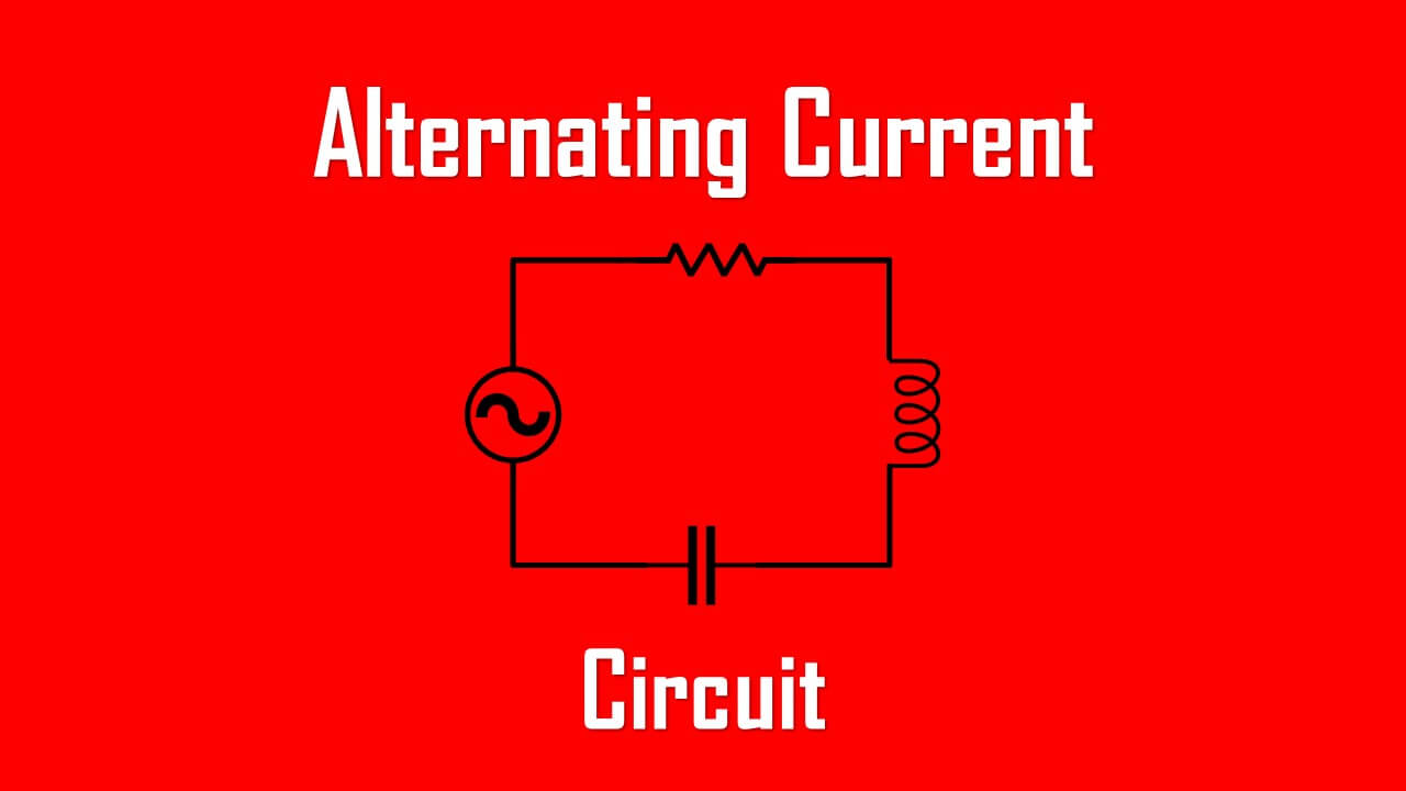
It will be a different story with an AC circuit where reactance generated by inductor and/or capacitor affects the circuit. The power dissipated in an AC circuit changes continuously both in direction and magnitude since it is a sinusoidal waveform.
For a starter, we need to remember two things:
- Inductance causes the current lagging behind the voltage (maximum of 90o)
- Capacitance causes the current leads ahead the voltage (maximum of 90o)
What is Power Factor Correction
Power Factor Correction or PFC is a circuit that uses parallel connection of capacitor to reduce the phase shift caused by inductive load or uses inductor to reduce the phase shift caused by capacitive load.
When we use a capacitor or inductor to correct the power factor in our circuit depends on the types of power factor in our circuit. The higher the power factor (reaching unity or 1), the more efficient the circuit works.
There are three types of power factor:
Unity Power Factor is a circuit whose current is in-phase with its voltage. The power factor is equal to 1 (unity). This is an ideal circuit with no reactive power in the circuit. We don’t need to correct the power factor.
Lagging Power Factor is a circuit whose current lags behind the voltage. This is caused by the excessive inductive load in the circuit. The power rating ranges from 0 to 1 but its phase angle between voltage and current is minus.
Leading Power Factor is a circuit whose current leads ahead the voltage. This is caused by the excessive capacitive load in the circuit. The power rating ranges from -1 to 0.
Before jumping to PF correction, we need to understand fully the types of power, they are:
- Real power (P) = usable energy transferred to the load (W). This is the total available power we can utilize fully.
- Reactive power (Q) = usable to generate magnetic fields in inductive or capacitive components (VAR). This power is transferred back to the supply causing a disturbance.
- Apparent power (S) = the combination of real and reactive power (VA). This is the total amount of consumed power in a circuit. This is why the electrical bill is charged based on apparent power even if the real power is the only power that can be fully utilized.

Power Factor Correction Example
There is no shortcut to use the power factor correction formula immediately. Normally we need to calculate the active power, reactive power, apparent power, and phase angle first of a circuit.
Then we decide the new power factor we desire and calculate the capacitance or inductance needed to mitigate the disturbance to the circuit.
For an example we will use a power factor correction capacitor to reduce waste on an RL circuit.
Assume we have a circuit with an inductive load so our circuit has its current not in-phase with voltage. Furthermore, the power factor is not unity.

The impedance is

The voltage VR across the resistor (or real power, P), voltage VL across the inductor (or reactive power, Q), and total power (or apparent power, S) are
We can calculate the phase angle using
![]()
Thus
The real power (P), reactive power (Q), and apparent power (S) are

The current lags behind the voltage by 63o with the power factor
![]()
In order to minimize the reactive power consumed by the inductor (645.25 VAR), we need to add more opposite reactance to the circuit.
Keep in mind that the power factor of 0.45 means we need 500VA to produce 225W of real power.
Since the inductive reactance is positive, we can add capacitive reactance which is negative to the circuit to make the power factor as close as 1 or unity.
Adding a capacitor in parallel with the inductor will minimize the reactive power.
Assume we want to increase the power factor from 0.45 to 0.90.
The phase angle is
![]()
The required VAR if we use the real power above is
This means our previous reactive power of 645.25 VAR needs to be corrected into 152 VAR. We need a capacitor to reduce 645.25 – 152 = 493.25 VAR.
The capacitive reactive power needed is 493.25 VAR thus the reactance should be
To balance out the inductive reactance, we need a capacitive reactance equal to 42.625 Ω at the same frequency.
The power factor correction equation is used when we have to calculate the capacitor needed to mitigate disturbance caused by an inductor, or an inductor to mitigate disturbance caused by a capacitor.
This time we need to calculate the capacitor needed to be added to the circuit.
From all this calculation, we need a 62.26 uF capacitor connected parallel to the inductor to improve power factor 0.45 to 0.90.
The new apparent power (S) volt-ampere value is

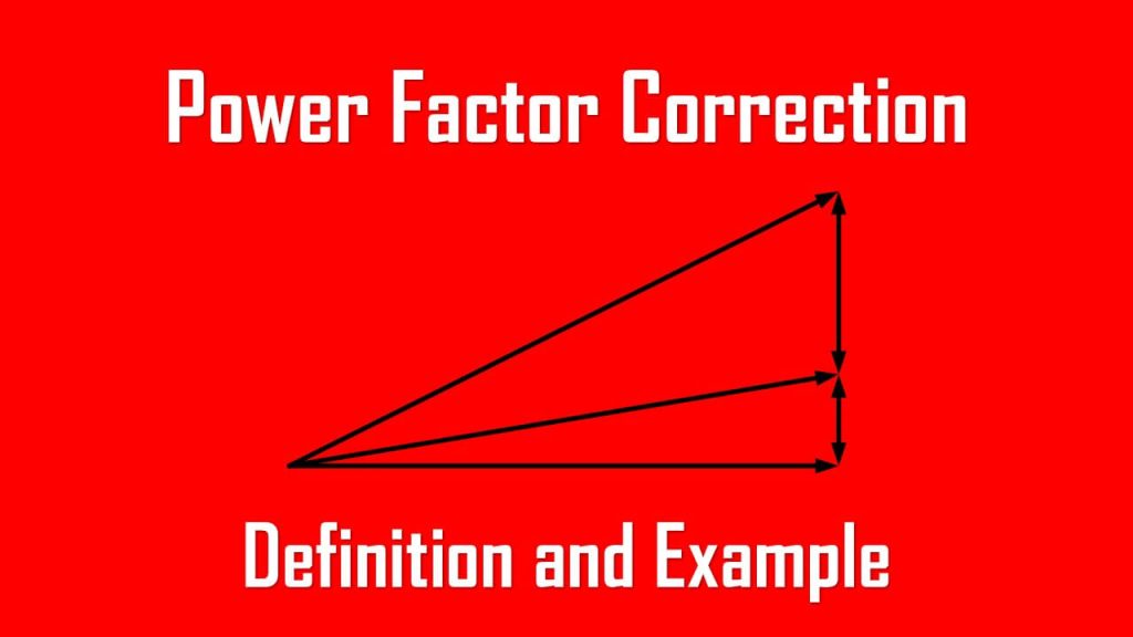
Below is the power factor correction triangle consisting of the before and after phase angle, apparent power (S), and reactive power (Q).

The current drawn from the supply is

This shows us the improved efficiency by looking to the 2.48 amperes drawn from the supply rather than 5 amperes.
Our power factor correction circuit consists of the previous RL circuit with a pfc capacitor connected parallel to them.

All of this step can be used to a capacitive circuit corrected by inductance load connected in parallel.