What Is an Electrical Circuit and How Does It Work?
Knowing exactly what is an electrical circuit will benefit us even if we are not trying to master it or study it further for a professional career. Even learning basic electrical circuit can make us able to fix simple broken electronics, such as flashlight, electric fan, TV remote, etc.
Before jumping into how to tweak and analyze a simple electric circuit, we need to able to answer these questions:
- What is the electrical circuit definition?
- What are the main components of an electrical circuit?
- How does an electric circuit work?
Just like what we have understand, electricity in a circuit is not visible to human eyes, therefore we could only use the pyshic theories, experiments, and calculation. But first, make yourself familiar with the definition of electricity first!
What is Electricity
Electricity is called physical phenomena related to the presence of matter which has the property of electric charge. Ages ago, electricity was considered not related to magnetism.
But after Maxwell’s demonstration, both magnetism and electricity are considered as a single phenomenon. The definition of electricity may be:
- Electricity is a form of energy.
- Electricity is a flow of electric charge
- Electricity is the flow of electrons.
If you type ‘what is electricity’, the explanation above is the simple definition of electricity. What is our concern is the electric charge.
This matter can be either positive or negative and produces an electric field. Its movement is called by electric current and is able to produce a magnetic field.
The first electric circuit was invented in 1800 by Alessandro Volta. He made the statement that connecting the bowls of salt solution with metal strips can produce a steady flow of electricity. He used a disc of copper, a salt solution soaked in cardboard, and zinc. His voltaic pile is known as an early battery. By connecting a battery with single copper wire from top to bottom, an electric current flows.
What is an Electrical Circuit
For an electrical circuit to work properly, a closed loop formation is needed. This loop is connected from head to tail just like a racing circuit. This is the basic idea of “circuitry definition”.
What is the simple electric circuit explanation?
An electric circuit definition is a “circuit” or “path” for the electric current to flow. Not only the path, but an electrical circuit consists of at least a component which is able to give electrical energy to the circuit and at least a component which is able to convert the electrical energy to a different form of energy.
The component to generate electrical energy can be a generator or a battery. The component to absorb and convert the electrical energy to a different form of energy can be electric motor, lamp, heater, computer, and many more.
Don’t forget that we need the other main components of an electric circuit, it is a “path” or “circuit”. It consists of conductor, wire, and other transmission line.
Simplifying the definition above:
An electric circuit is an interconnection of several electrical components so that the electric charge can flow along in a closed path or closed circuit.
Simple Electric Circuit Example
Electrical circuits contain active and passive electric elements such as resistors, inductors, capacitors, transformers, switches, and many more.
It is very important to learn the parts of electrical circuits, their symbols, and their functions.
An electric circuit is an interconnection of electrical elements.
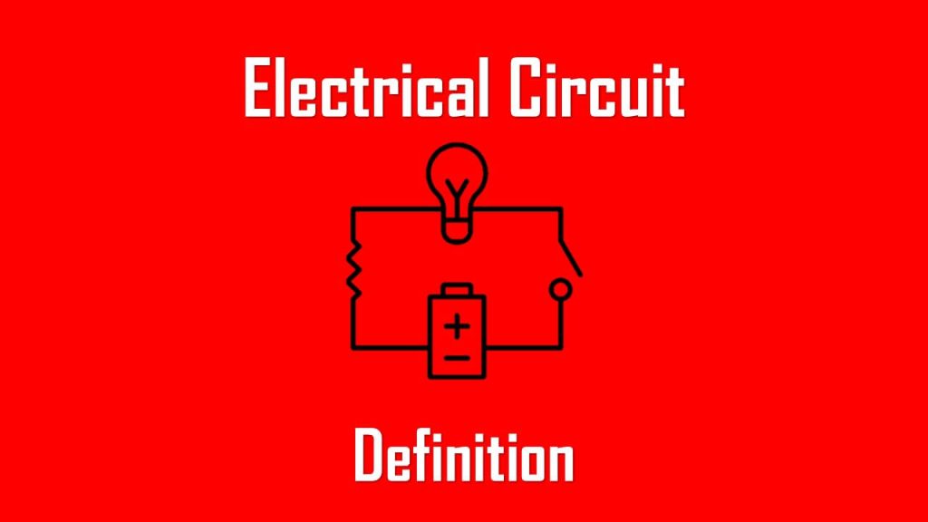
Summary, you can call an electrical circuit as a path or transmission line where an electric current flows through. If the circuit is joined from the start to the end of the line, we call it ‘closed-loop’.
This circuit makes the electric currents able to flow. Otherwise, we call it an ‘open circuit’ where the circuit is not connected at both ends and the electric currents can’t flow.
If you still can’t follow my lead, then to make it super easy, you can check the illustration below. This is the simple electric circuit implementation where we build a flashlight. This simple electric circuit represents basic components of an electric circuit.
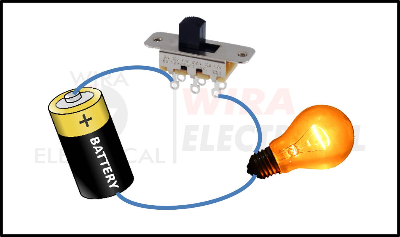
In the circuit above, you can find all the three main elements of what form an electrical circuit.
- First, the battery is the element which supplies the circuit
- Second, the lamp is the element which converts the electric energy into another form of energy, in this case is lighting from the light bulb.
- Third, the connection wire which makes a closed-loop circuit. This makes the electric current flow from the battery to the load (lamp) and back to the negative polarity of the battery.
The switch is only an addition to the circuit to control when the lamp is ON or OFF.
If the switch is open then there is no current flowing in the circuit and the lamp is OFF because the circuit is open-circuit. When we close the switch, the circuit becomes closed circuit and current is flowing in the circuit then turning ON the lamp.
Now you have understood the term of electrical circuit definition. Keep in mind that an open-circuit can be considered as an electrical circuit, but it can’t make the electric current flow.
What are the main components of an electrical circuit? They are:
- Power souce: it can be voltage source or current source, an element to provide power to the circuit.
- Load: an element that convert electrical energy into another form of energy (for example, light bulb or electric motor).
- Conductor path: providing path for electric current to flow between two points.
- Switches: an extra component to control when will the circuit is closed (ON) or opened (OFF)
How Does an Electric Circuit Work?
An electric circuit can work if the circuit is a closed-loop, then the current can flow through the system. One thing to remember, we need the electrons to be able to move throughout the circuit, from the positive pole to the negative pole of a power source.
An electrical circuit is a path or line where electric current can flow through. The usage of a battery or any power source will produce a force to make the electrons move through end to end of a path.
The simplest example of interconnection is a flashlight circuit. The circuit has three basic elements: a lamp, connecting wires (or conductor wires), and a battery.
If we don’t learn about electrical engineering, we may find it useless.
Now let us apply interconnection to these things. Connecting them all together with the right decision will give us a flashlight.
Electrical Circuit Symbols
If you are designing, analyzing, or fixing an electrical circuit, you need to know every electronic component along with the electronic symbol in the circuit or every electric circuit symbol you should use. When we are dealing with a circuit, we will most likely deal with its circuit diagram.
Circuit diagram shows the connection of a bunch of electrical components in that circuit. You will absolutely need this to do your job very well. Imagining the circuit without drawing it is very hard, especially for the complex circuit.
The electronic symbols can be divided into:
- Connection wire
- Power supply or power source
- Output device
- Switch (electric or manual)
- Basic components such as resistor, capacitor, and inductor
- Diode
- Transistor
- Audio
- Meters such as voltmeter, ammeter, galvanometer, ohmmeter, power meter, and oscilloscope
- Sensors
- Logic gates
- Integrated circuit
- Operational amplifier
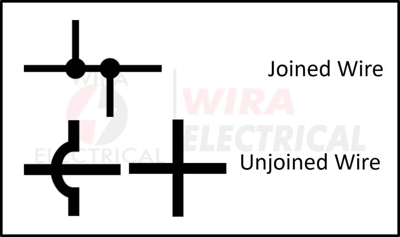
Connection Wire Symbols
We will find a lot of intersections of wires in a circuit. Make sure to understand what are the types of intersection here,
We use this to connect component to component and make an electrical circuit. This is a conductor as a path for the current to flow. The symbol is very simple, just a straight line.
- Joined wire = a node, a junction, or an intersection. Often used in Kirchhoff’s Laws.
- Unjoined wire = a crossroad that is not connected to each other. Sometimes it is replaced with curved line to make a clearer path.
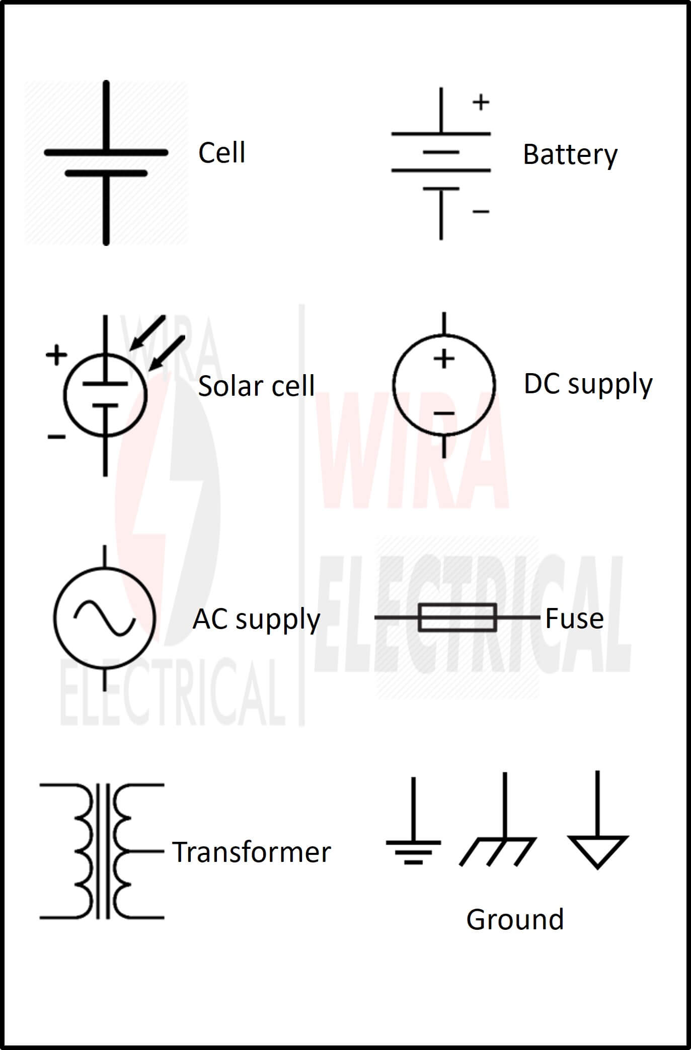
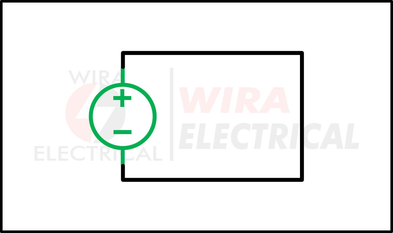
Power Circuit Symbols
This element energizes a circuit with either voltage or current.
- Cell / battery = provides electricity with a fixed one direction polarity,
- Photovoltaic cell = provides electricity from the conversion of the solar energy,
- DC supply = supplies the electrical energy in direct current form similar to batteries.
- AC supply = supplies the electrical energy in alternating form.
- Fuse = protection device to cut the circuit whenever the current surpasses the specified amount and capability,
- Transformer = used to step-up or step-down AC voltage. Mainly used in electronics and residential power distribution,
- Ground / earthing = prevent a zap in the circuit when touched.
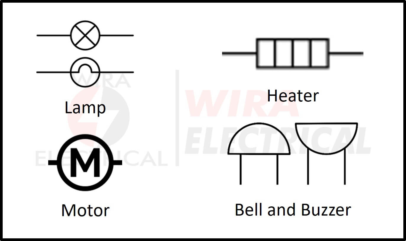
Output Devices Symbols
These elements convert the electrical energy into different forms of energy.
- Lamp (lighting and indicator) = converts electricity energy into light,
- Heater = converts electrical energy into heat,
- Motor = converts electrical energy into kinetic energy, and
- Bell or buzzer = converts electrical energy into sound output,
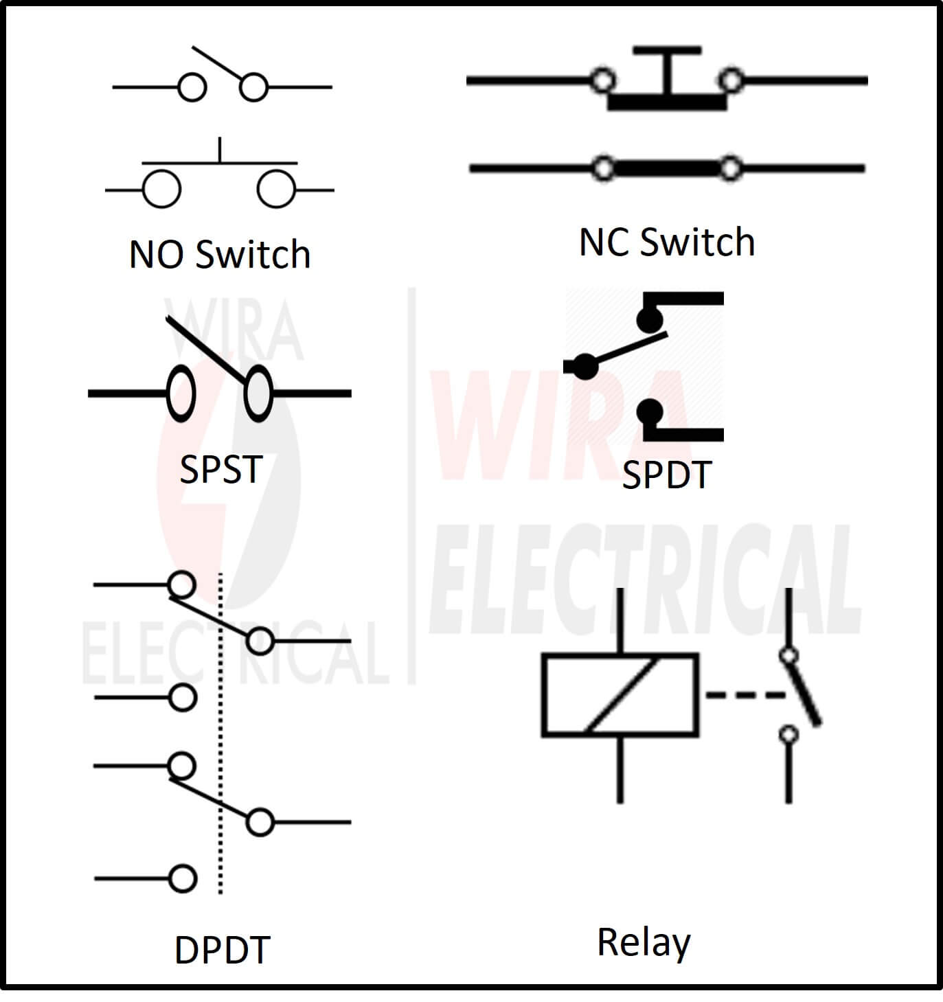
Switch Symbols
This element is used to control the current flow in the circuit.
- NO (Normally Open) = a switch which is in a closed state when pressed or triggered,
- NC (Normally Close) = a switch which is in an open state when pressed or triggered,
- Single Pole Single Throw (SPST) = an NO or NC switch with one route,
- Single Pole Double Throw (SPDT) = a two-conditions switch which is able to switch the current flow depends on the route,
- Double Pole Double Throw (DPDT) = similar to SPDT but has two output that can be applied as a reversing switch for a motor, and
- Relay = a famous electrical switch has so many varieties of configuration.
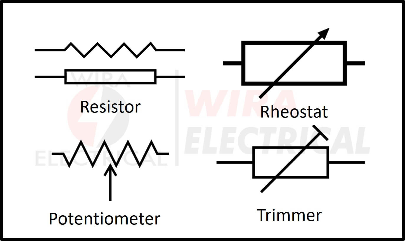
Resistor Symbols
This component is used to control the current in the circuit. Resistor provides resistance in the circuit, limiting how much current flows.
- Rheostat variable resistor = can be set to be a specific value of resistance in its resistance range,
- Potentiometer variable resistor = a variable resistor that has 3 ports and one of them is used as a transducer converting position to an electrical signal. Other words, this is used for Analog-to-Digital Converter,
- Preset variable resistor (trimmer) = uses a screwdriver to be set to adjust the resistance.
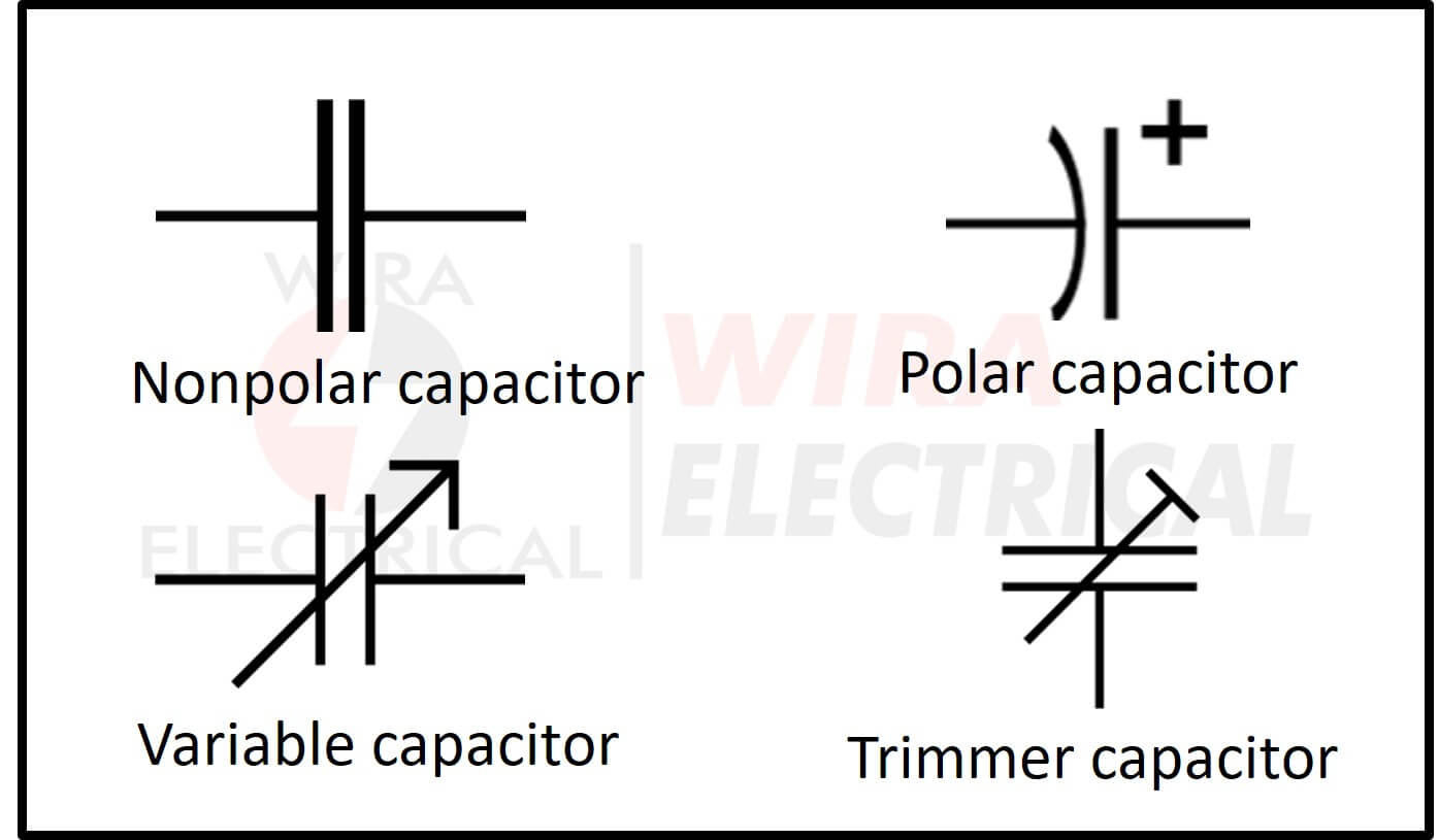
Capacitor symbols
This component is used to provide capacitance in the circuit.
- Nonpolar capacitor = doesn’t have polarity and is able to charge electric voltage,
- Polar capacitor = the polarity needs to be connected in the correct way and this capacitor has larger capacitance,
- Variable capacitor = a variable capacitor as a radio tuner for example, and
- Trimmer variable capacitor = can set the capacitance for the capacitor.
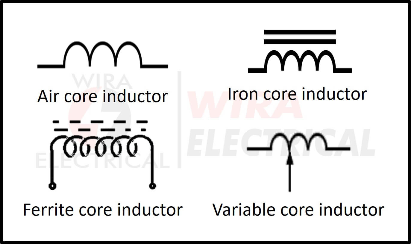
Inductor Symbols
The inductor itself has some version of it such as,
- Air core inductor = has no core or air core,
- Iron core inductor = has iron as its core,
- Ferrite core inductor = has ferrite as its core, and
- Variable core inductor = can adjust the inductance for this type.
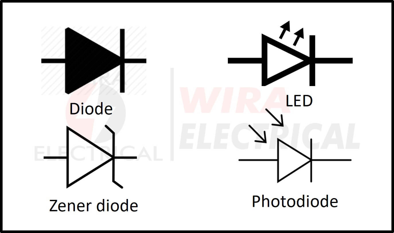
Diode Symbols
Diode is a component to prevent the current flow in the opposite direction.
- LED (Light Emitting Diode) = able to emit light when the current flowing passes this diode,
- Zener diode = works as opposite as the normal diode one and can be used to maintain a fixed voltage, and
- Photodiode = has high sensitivity to the light.
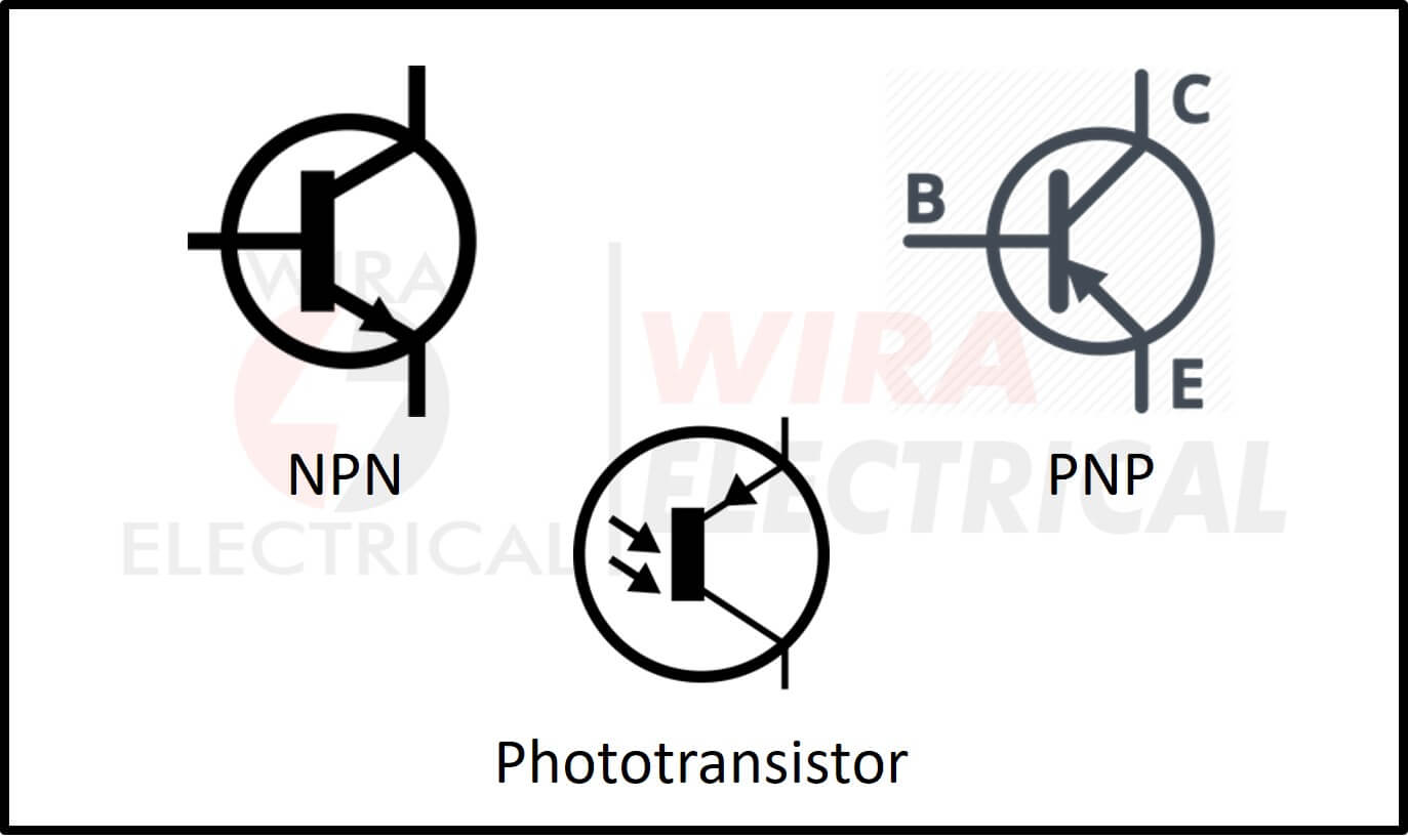
Transistor Symbols
We can use this as an amplifier or a switch.
- Transistor NPN = a transistor with NPN pin,
- Transistor PNP = a transistor with PNP pin, and
- Phototransistor = a transistor with high sensitivity to the light.
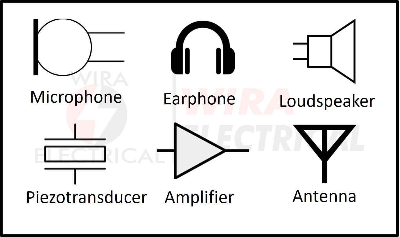
Audio Symbols
This element converts the electrical energy into sound or other way around.
- Microphone = converts sound to electric signals,
- Earphone = a device to listen to audio in the form of an electric signal privately,
- Loudspeaker = converts electric signal into audio output to be transmitted in the open air,
- Piezo transducer = converting pressure force to electrical energy,
- Amplifier = amplifies electrical signals, and
- Antenna = receives or transmits the signals.
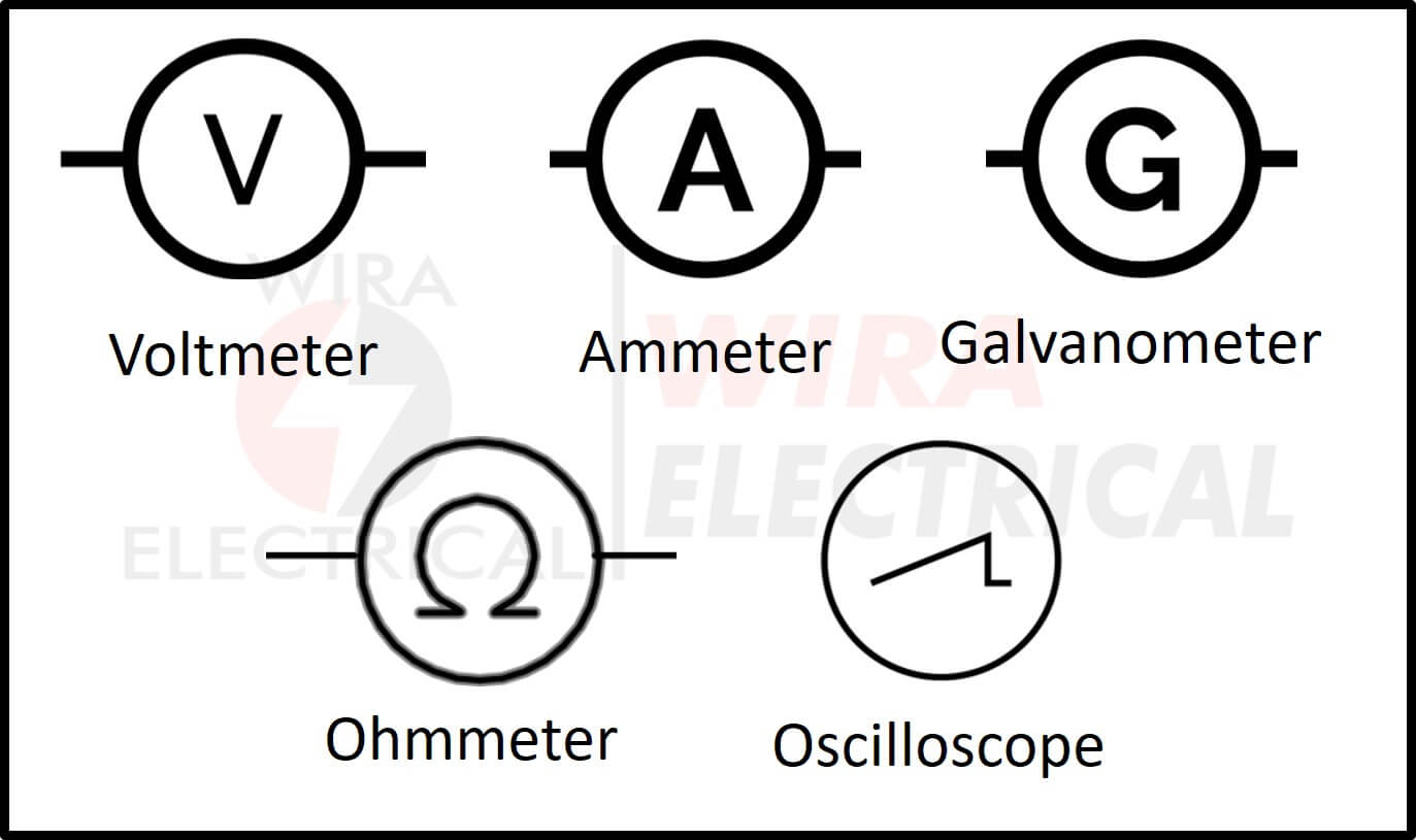
Meter Symbols
Meters are the measurement tools for any electrical parameter in the electrical circuit.
- Voltmeter = tool to measure the electric voltage,
- Ammeter = tool to measure the amperage of electric current,
- Galvanometer = a sensitive tool using an armature and a set of magnets,
- Ohmmeter = tool to measure the resistance, measured in ohm, and
- Oscilloscope = A digital meter which is able to display the waveform as an electrical signal. We can tune the period, measurement scale, and even save the image.
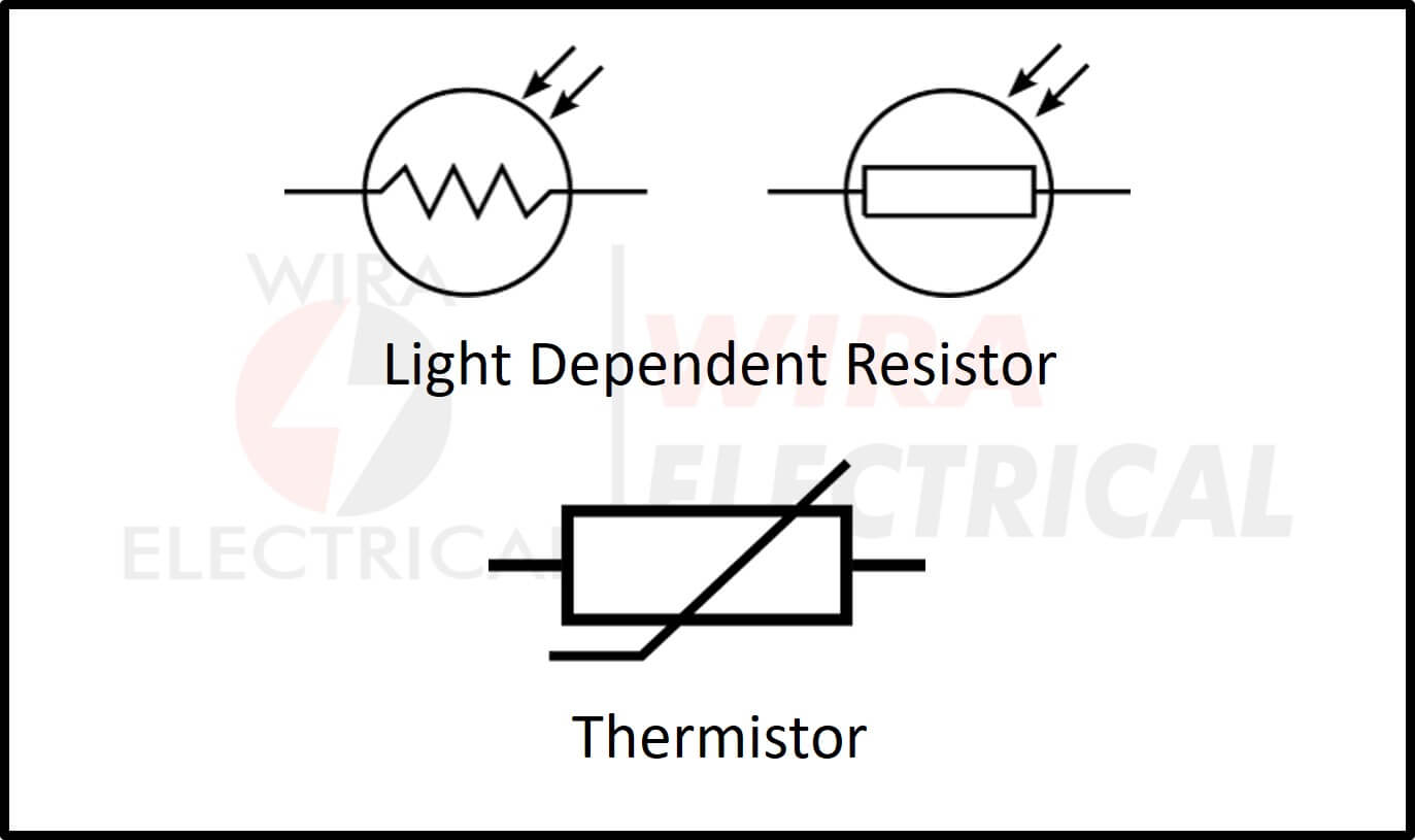
Sensor Symbols
This element is capable of receiving energy and converts it into electrical signals.
- Light Dependent Resistor (LDR) = a component which is able to convert light into electrical signal or voltage, and
- Thermistor = a component which is able to convert the temperature into electrical signal or voltage.
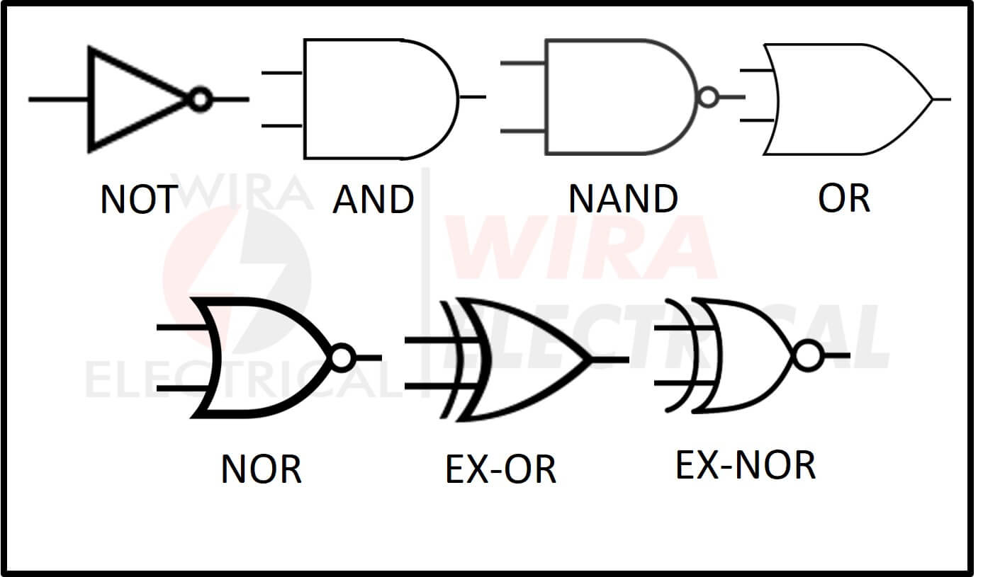
Logic Gate Symbols
Logic gates are used to design a digital sequence program for electronics.
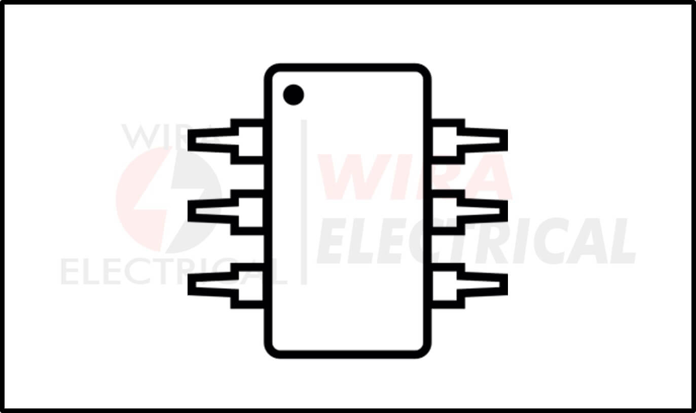
Integrated Circuit (IC)
This type has various applications and is very convenient to use. Usually, it is drawn with a rectangular shape and some ports.
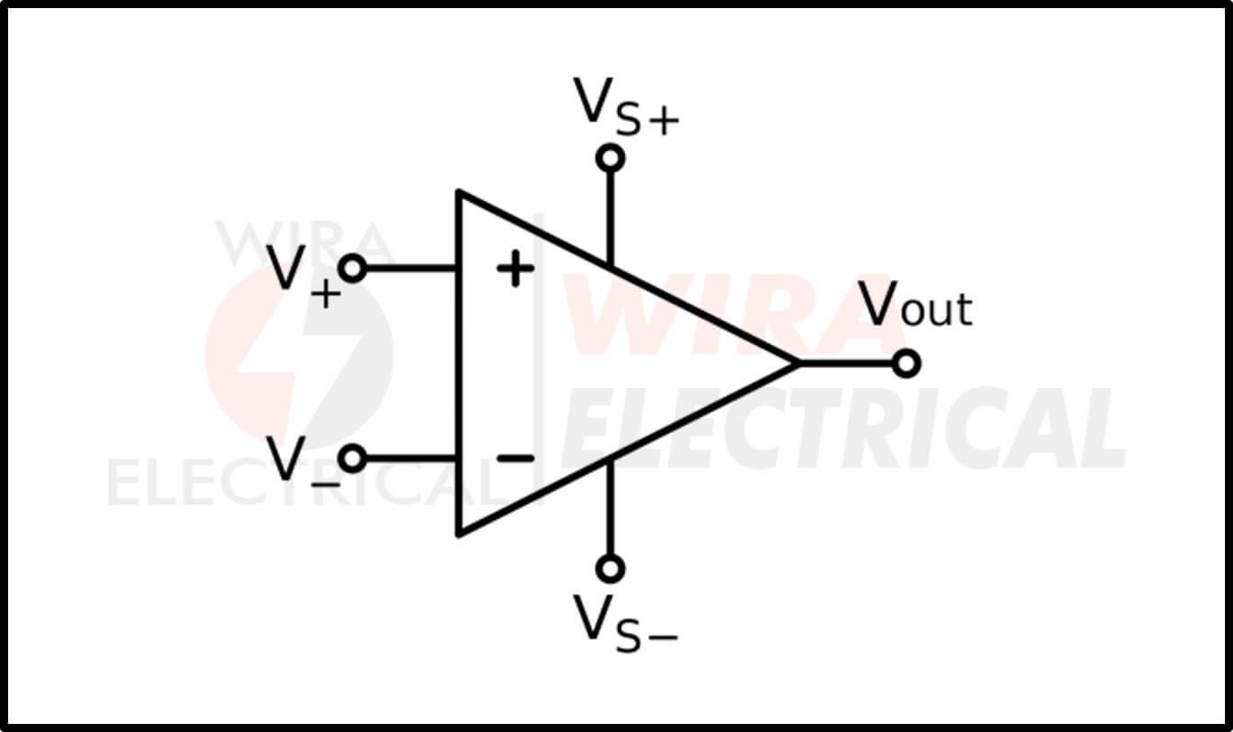
Operational Amplifier
It is also popular with Opamp and is illustrated with a triangle shape along with three ports: two as inputs and one as output.
Types of Electrical Circuits
If we are talking about the types of electrical circuits, we will find the two very basic types. The first one is a series circuit and the second is a parallel circuit. Their basic difference is how many loops they have in their circuit. You can check the example below; you will understand it faster.
Series circuit
The series circuit has one loop from end-to-end, from the source back to the source. If we cut the wire in any position or remove one of the elements except for the source, that spot is an open circuit and the current will stop flowing.
You can see the example below.
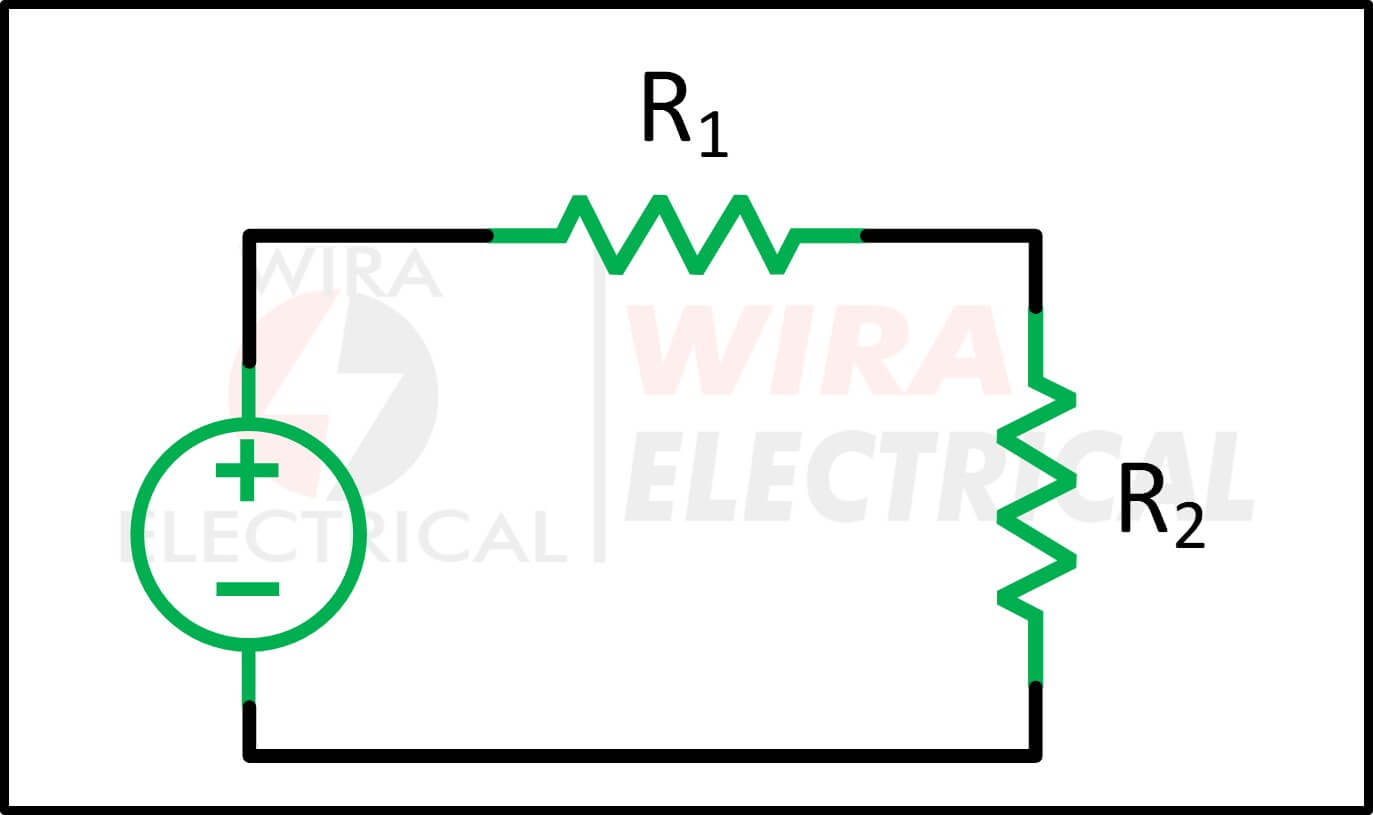
In a series circuit, the current in the circuit will be the same for every element in there. Summary, the current passing through R1 and R2 will be the same value. If we remove one of the resistors then the circuit will be an open-circuit and the current will stop flowing.
That’s the essential thing about series circuits. Another simple example of a series circuit is a flashlight. We just need to connect a battery, switch, and lamp in one path. Once you open the switch then the lamp will be turned off.
Parallel circuit
The parallel circuit has more than one loop for the current to flow. If we cut the wire in any position or remove one of the elements except for the source, that spot is an open circuit but the current can still flow through another loop.
You can see the example below.
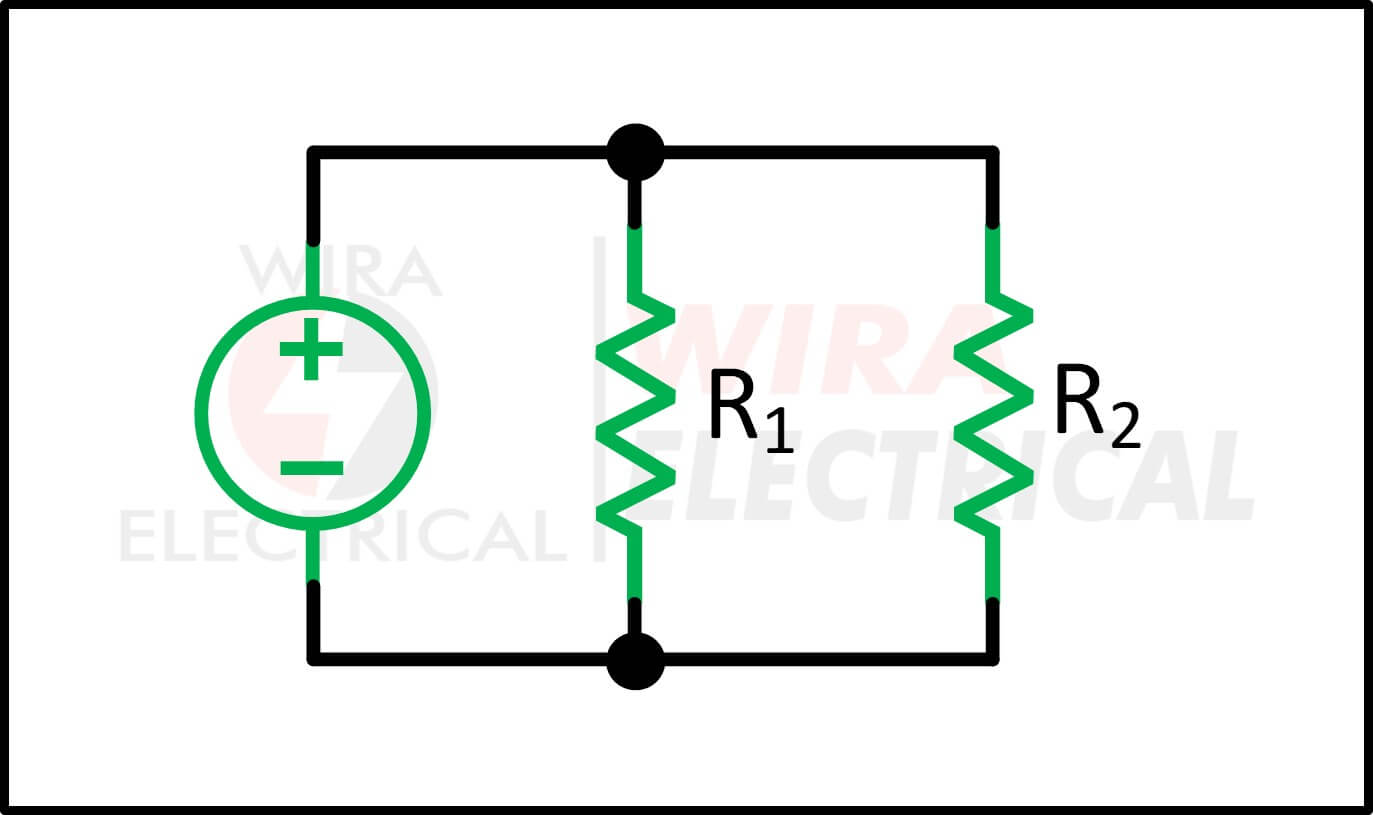
In a parallel circuit, the current in the circuit will be the sum of all the current in every loop. The current in each loop depends on the load in that loop. If we remove the R1 then the current through R1 will start flowing through the R2. If we remove the R2 then the current through the R2 will start flowing through R1.
Summary, if we cut one loop then the current will start flowing in another loop as long as there is a loop which is still a close-circuit.
Closed circuit
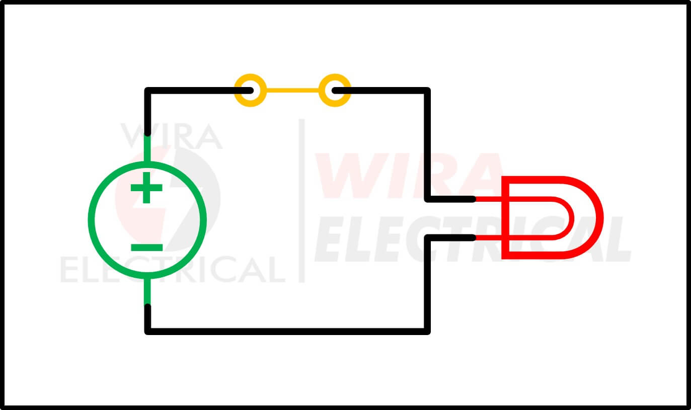
This is the circuit where the circuit is connected end to end and the electric charges are able to move through the system.
This circuit is the same with the flashlight circuit when you turn on the switch.
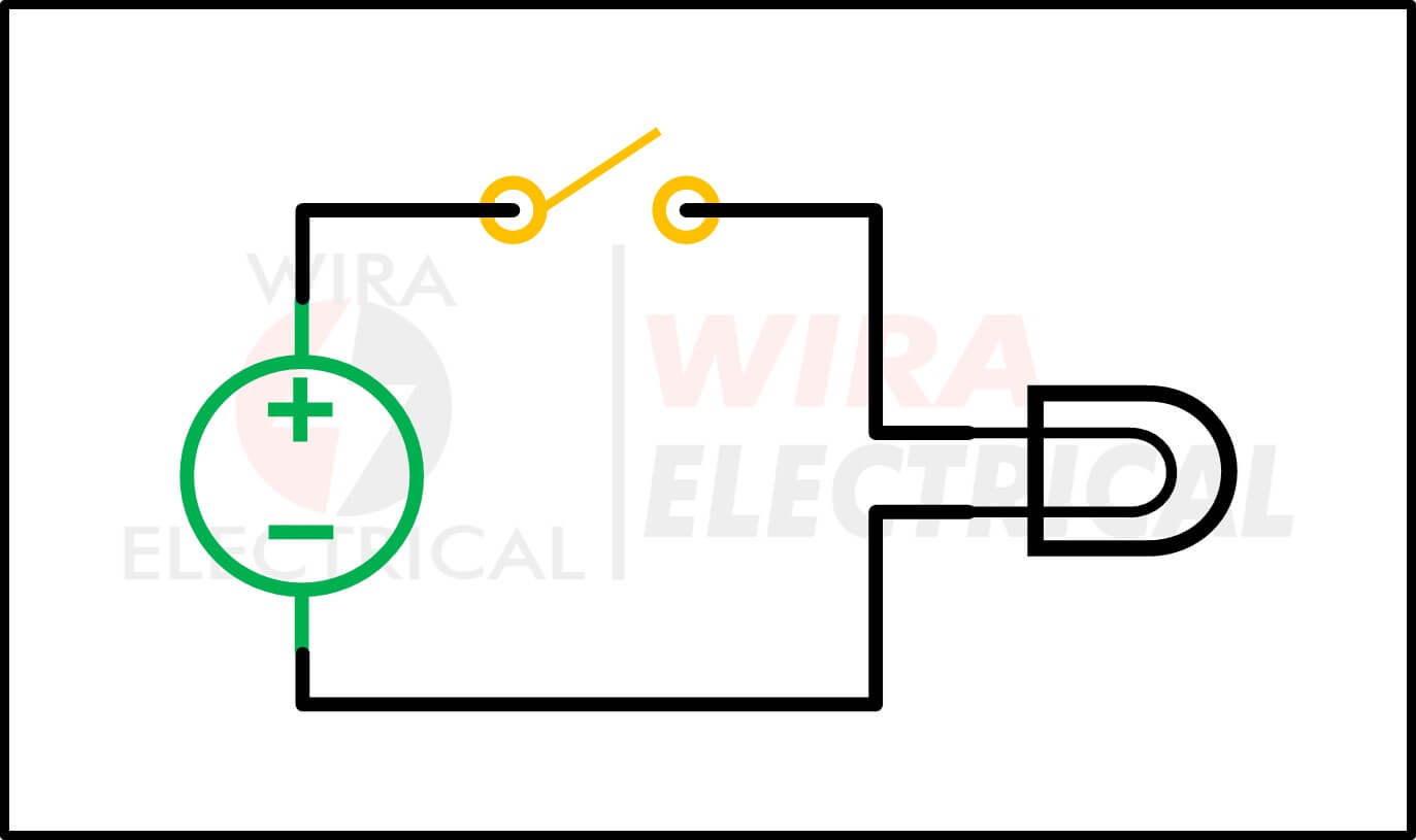
Open circuit
You will find something strange in this circuit where the circuit is not connected in a specific place. Electric charges are not able to move in this circuit.
The example of this circuit is when you turn off the switch of a flashlight.
Short circuit
What is a short in an electrical circuit? Short circuit is a circuit when the current is too large. This can occur if there is no load in a conductor wire connected to a power source.
It is like connecting the positive polarity and negative polarity of a battery with copper wire.
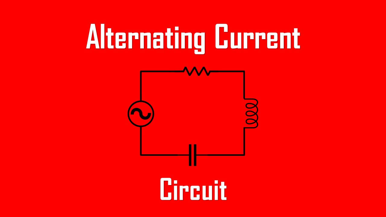
Electric Circuit AC and DC
We will encounter a lot of electric circuits in life applications. The application of an electric circuit will result in a different type of electrical circuit. For starting, the electric circuit types will differ as:
The difference between these two is the source of the corresponding electric circuit. If the dc source energizes the circuit, it will be a dc circuit.
On the other hand, an ac circuit happens if the ac source energizes the circuit. Make sure to read both before leaving to advance matters.
Other than the explained above, electrical circuits are also used for electronic filters.
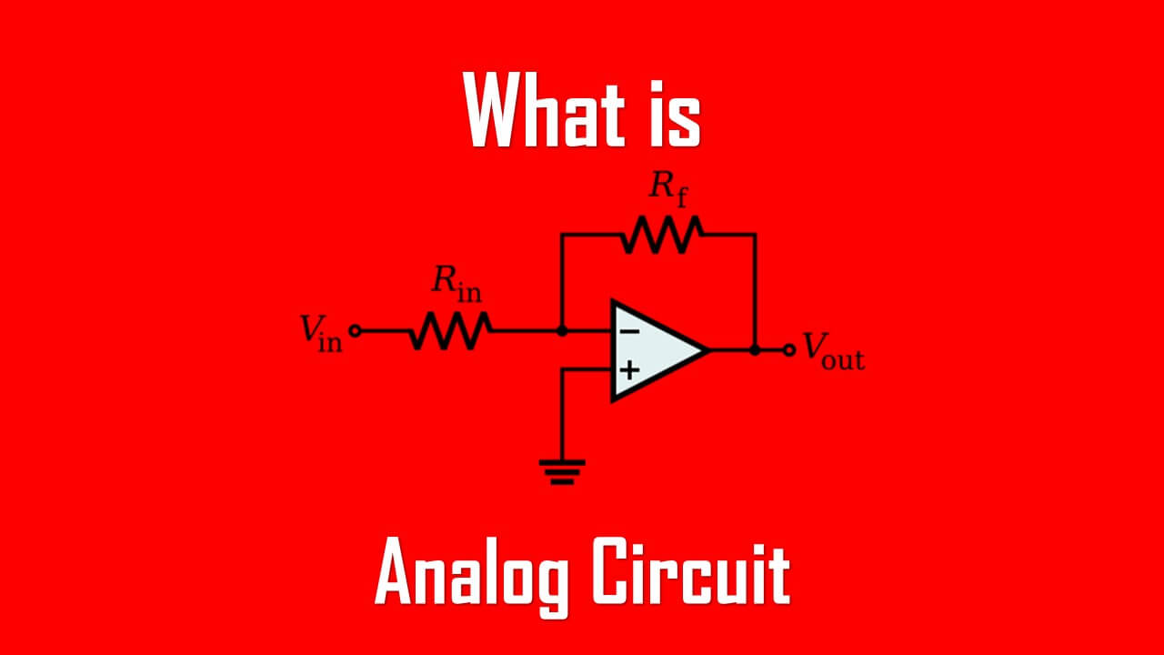
Analog vs Digital Circuits
Both analog and digital circuits are able to receive electrical signals. But what forms of signals they are able to process is what makes them different.
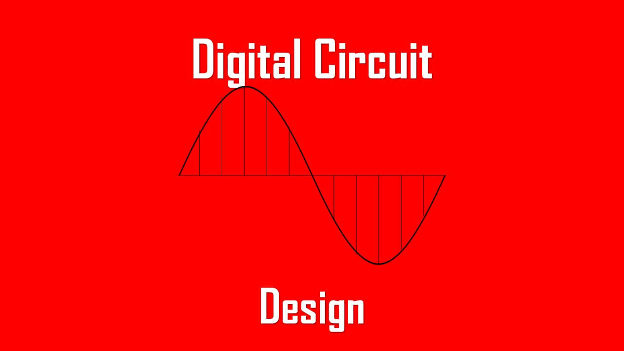
- A digital circuit only has two states 0 and 1. The digital circuit itself is made for the purpose of digital electronics. Digital circuits process discrete values.
- An analog circuit is able to process real numbers. These numbers are processed to produce any value in the line, integer or decimal numbers. Analog circuits which process analog signals.
Both digital circuits and analog circuits have their own strengths and weaknesses so we can’t disregard one to another.
Electronic Filter Definition
You meet electronic filters in audio crossovers, phone chargers, and power supplies. They shape frequency content:
- Low-pass = passes the low frequency lower than the cutoff frequency, keeps bass, blocks noise.
- High-pass = passes the high frequency higher than the cutoff frequency, keeps treble, reduces hum.
- Band-pass = passes the frequency between two desired values.
In power circuits, simple electronic filters smooth rectified DC for cleaner electronics.
References
- IEC 60050 — International Electrotechnical Vocabulary.
- NFPA 70 (NEC) — National Electrical Code (latest edition).
- IEEE Std 100 — The Authoritative Dictionary of IEEE Standards Terms.
- Horowitz & Hill — The Art of Electronics (practical electronics reference).