What is Phasor and Phasor Diagram Simple Explanation
Phasor can be used to express sinusoidal easily, which is a convenient method to do rather than sine or cosine functions.
Phasor is a complex number that represents the amplitude and phase of a sinusoidal.
Phasors give a simple method to analyze linear circuits excited by sinusoidal sources. The effort to solve ac circuits using this term was introduced by Charles Steinmetz in 1893.
Before we learn about phasors, we need to get better on complex numbers.
Make sure to read what is ac circuit first.
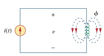
Read also : parts of a transformer
Phasor Diagram
A complex number z can be expressed in rectangular form as
 |
| (1a) |
where j = (√-1); x is the real part of z; while y is the imaginary part of z.
This time, x and y do not refer to a coordinat or location as in analytical of two-dimensional vector but rather the real and imaginary parts of z in the complex plane.
Though, there will be still an act to manipulate complex number with two-dimensional vector analysis method.
The complex number z can also be represented in polar or exponential form like
 |
| (1b) |
where r is the magnitude of z, and ∅ is the phase of z. We can conclude that z can be expressed in three ways :
 |
| (2) |
The relationship between the rectangular form and the polar form can be seen in Figure.(1), where the x-axis represents the real part while the y-axis represents the imaginary part.
 |
| Figure 1. Representation of complex number z |
Given x and y, we can calculate r and ∅ as
 |
| (3a) |
On the other side, if we have r and ∅, we can calculate x and y by
| (3b) |
Hence, z can be written as
 |
| (4) |
Subtraction and addition from complex numbers are easily done in rectangular form; multiplication and division are easily done in polar form.
With the complex numbers :
 |
| (5) |
and we can use the following operations :
Addition :
 |
| (6a) |
Subtraction :
 |
| (6b) |
Multiplication :
 |
| (6c) |
Division :
 |
| (6d) |
Reciprocal :
 |
| (6e) |
Square Root :
 |
| (6f) |
Complex Conjugate :
 |
| (6g) |
Notice from Equation.(6e),
 |
| (6h) |
These are the needed basic operation of complex numbers. The basic idea of representation of phasor is based on Euler’s identity. In general,
 |
| (7) |
which shows that we may regard cos∅ and sin∅ as the real and imaginary parts of ej∅; we can write
 |
| (8a) |
 |
| (8b) |
where Re and Im are the real part of and the imaginary part of. Given an sinusoidal example v(t) = Vm cos(ωt + ∅), we use Equation.(8a) to express v(t) as
| (9) |
or
 |
| (10) |
Thus,
 |
| (11) |
where
 |
| (12) |
Hence, V is the phasor representation of the sinusoidal v(t), as we learned before.
Namely, a phasor is a complex representation of the magnitude and phase of a sinusoidal.
We can use either Equations.(8a) or (8b) to build a phasor, but the standard convention belongs to Equation.(8a).
One time to look at Equations.(11) and (12) is to notice the plot of the sinor Vejωt = Vmej(ωt + ø) on the complex plane.
As time increase, the sinor move rotational on a circle of radius Vm with an angular velocity ω in a counter-clockwise direction, as drawn in Fig.2(a).
We may assume v(t) as the projection of the sinor Vejωt on the real axis, as drawn in Fig.2(b).
The value of sinor at time t = 0 is the phasor V of the sinusoidal v(t). The sinor can be assumed as a rotating phasor.
Hence, whenever a sinusoidal is developed as a phasor, the term ejωt is implicitly present.
We need to keep in mind on the frequency ω of the phasor, otherwise, a huge mistake can be made.
 |
| Figure 2 Representation of Vejωt : (a) sinor rotating counterclockwise, (b) its projection on the real axis, as a time function |
Equation.(11) refers that in order to obtain sinusoid with a given phasor V, multiply the phasor with the time factor ejωt and take the real part.
A phasor can be expressed in rectangular form, polar form, and exponential form.
Phasor behaves like a vector and is written with bold font because it has magnitude and phase (direction).
For example, V = Vm∠∅ and I = Im∠∅ are graphically drawn in Figure.(3).
The name of the graphical drawing is known as phasor diagram.
Equations.(9) through (11) show that we may first express the sinusoid in the cosine form so that the sinusoid can be developed as the real part of a complex number to get the phasor corresponding to a sinusoidal.
After that, we take the time factor ejωt, and whatever is left is the phasor corresponding to the sinusoidal. This transformation method is written below :
 |
| (13) |
 |
| Figure 3. Phasor diagram of V = Vm∠∅ and I = Im∠∅ |
Assume we have a sinusoid v(t) = Vm cos(ωt + ∅), we get the corresponding phasor as V = Vm∠∅.
Equation.(13) is also presented in Table.(1), where the sine function is considered in addition to the cosine function.
From Equation.(13), we assume that in order to get the representation of phasor from a sinusoid, we can express it in cosine form and take the magnitude as the phasor and the argument as ωt plus the phase of the phasor.
 |
| Table 1 |
Notice that in Equation.(13) the phasor’s frequency (or time) factor ejωt is suppressed, and the frequency is not explicitly shown in the phasor domain representation because ω is constant.
Nevertheless, the response depends on ω. For this reason, the phasor domain is also known as the frequency domain.
From Equations.(11) and (12), v(t) = Re(Vejωt) = Vm cos(ωt + ∅), hence
 |
| (14) |
From the equations above, the derivative v(t) is transformed to the phasor domain as jω.
Differentiating a sinusoid is equivalent to multiplying its corresponding phasor by jω.
 |
| (15) |
Likewise, the integral of v(t) is transformed to the phasor domain as V/jω. Integrating a sinusoid is equivalent to dividing its corresponding phasor by jω.
 |
| (16) |
Equation.(15) and (16) are a handful for finding the steady-state solution, which does not require knowing the initial values of the variable involved.
Another important application of phasors is discovered in summing sinusoidals of the same frequency.
- v(t) is the instantaneous or time-domain representation, while V is the frequency or phasor domain representation.
- v(t) is time-dependent, but V is not.
- v(t) is always real with no complex term, but V is generally complex.
From above, we conclude that phasors analysis applies only when the frequency is constant; it applies in manipulating two or more sinusoidal signals only if they are of the same frequency.
We will move on to the:
- Basic phasor and the element
- Impedance and admittance
- Kirchhoff’s laws for ac circuit
- Power calculation in ac circuit
- Three phase ac circuit
And its applications:
Example of Phasor Diagram
1. Evaluate these complex numbers :

Solution :
(a) Using polar to rectangular transformation,

Adding them results
Taking the square root of this,
(b) Using polar-rectangular transformation, addition, multiplication, and division

2. Transform these sinusoids to phasors :

Solution :

(b) Since -sin A = cos(A + 90o),

The phasor form of v is

3. Find the sinusoids represented by these phasors :

Solution :
(a) We rewrite it to

Transforming this to the time domain gives
(b) Since j = 1∠90o,

Converting this to the time domain results

4. Given i1(t) = 4 cos(ωt + 30o) A and i2(t) = 5 sin(ωt – 20o) A, find their sum.
Now we see the important application of this term: to find the sum of the same frequency. Current i1(t) is in the standard form. Its phasor is

We have to express i2(t) in cosine form. The rule of converting sine to cosine is to subtract 90o. Thus,
and

If we let i = i1 + i2, then

Transforming the result to the time domain results