Alternating Current Circuit: Fundamentals, Formulas, and Real-World Insight
Basic Theory of Alternating Current Circuit
In alternating current circuit theory, an AC circuit is an electrical circuit supplied by an AC voltage thus its current will flow from positive to negative, then from negative to positive polarity, as we understood in Sinusoidal Waveform.
The AC circuit will have its amplitude oscillating between positive value, zero, and negative value. This oscillating voltage and current is repeated in a specific interval of times. There are various waveforms in an AC circuit but we will study the sinusoidal waveform because it is the most common.

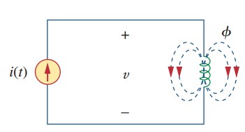
Now we will make a simple Alternating Circuit, consisting of an AC voltage source and a resistor. Observe the alternating current circuit diagram below consists of an AC voltage source and a resistor.

The illustration above tells us the direction of the current in an alternating current circuit. For a specific time, the current will flow from positive to negative polarity and then it will flow from negative to positive polarity. This will repeat from time to time, forming an oscillating waveform.
Since the load is only resistive, the voltage and current will have the same phase but different amplitude (depending on the load). It will be a different story if the circuit has inductive and/or capacitive load. We will study this later.
Commonly, we use these two equations to represent AC voltage and current
$$
\begin{aligned}
v(t)=V_m\sin(\omega t + \phi)\\
i(t)=I_m\sin(\omega t + \phi)
\end{aligned}
$$
The waveform will repeat after one period, or each internal time T = 2π/⍵ is achieved. Half of the period (0 – T/2), the voltage and current will have positive value then they have negative value for the second half of the period (T/2 – T).
Power in Alternating Current Circuits Explained
Power in AC circuits is a little trickier than in DC. That’s because voltage and current don’t always line up in time. When they do, all the energy delivered is doing useful work. When they don’t, some energy is just “sloshing” back and forth between the source and reactive elements (inductors and capacitors).
Just as mentioned above, an AC circuit can be purely resistive, inductive, capacitive, or combination two or three of them. Unlike a DC circuit where inductive and capacitive do not affect its waveform, inductive and capacitive load will affect the AC circuit.
The current may not have the same phase, shape, or frequency with the voltage.
Observe the sinusoidal waveform below to represent alternating current.

From the waveform above, we will find various variables such as:
- Amplitude
- Frequency (f)
- Period (T)
- Waveform
- Cycle
- Phase
- Etc.
When the voltage and current reach their maximum amplitude at the same time, we can conclude that voltage and current are in phase.

Not only that, when calculating the AC circuit we will use the RMS (Root Mean Square) value to make it easier. When using this, Ohm’s Law can also be used.
$$
\begin{aligned}
I_{rms}=\frac{I_{max}}{\sqrt{2}}\\
V_{rms}=\frac{V_{max}}{\sqrt{2}}
\end{aligned}
$$
Thus the Ohm’s Law is
$$
\begin{aligned}
V_{rms}=I_{rms}\times Z
\end{aligned}
$$
The Three Powers — Real, Reactive, Apparent
- Real power (P) — measured in watts (W). This is the portion that performs actual work: lighting a bulb, turning a motor, heating a coil.
- Reactive power (Q) — measured in volt-ampere reactive (var). This represents energy alternately stored and returned by inductors and capacitors.
- Apparent power (S) — measured in volt-amperes (VA). This is the product of RMS voltage and RMS current, without regard to phase.
Mathematically:
$$
\begin{aligned}
S &= V_{RMS} \times I_{RMS}\\
S &= \sqrt{P^2 + Q^2}\\
\mbox{Power Factor} &= \cos\phi = \frac{P}{S}
\end{aligned}
$$
Where \(\phi \) is the phase angle between voltage and current. If \( \phi = 0, \mbox{PF} = 1 \) and all current contributes to real power. If not, part of the current only supports reactive power.
Practical note: utilities often bill commercial customers for low power factor. Fixing PF with capacitors or active filters usually pays back quickly.
AC Circuit Reactance and Impedance — Quick Recap
We already touched on reactance briefly, but here’s the clean summary you’ll want bookmarked.
- Inductive reactance: \( X_L = 2 \pi f L \) (current lags voltage)
- Capacitive reactance: \( X_C = \frac{1}{2 \pi f C} \) (current leads voltage)
- Impedance (for series R-L-C): \( Z = R + j(X_L – X_C) \) and \( |Z| = \sqrt{R^2 + (X_L – X_C)^2} \)
In AC circuit analysis, treat \( j \) as a 90° rotation operator. That makes algebraic manipulation straightforward compared to time-domain calculus.
Inductive Reactance
Inductor provides inductance, which is a component that is able to store and release electricity in the form of a magnetic field. An AC circuit that is inductive will have its current waveform distorted compared to its voltage.

In an AC circuit with RL load, the back EMF (electromotive force) will be generated in the inductor (since it is a coil). It needs some time to fully charge it with a magnetic field.
The inductive reactance and inductance have a relationship as shown below.
\( X_L = 2 \pi f L \)
Where:
\( X_L \) = inductive reactance, measured in Ohms (Ω)
\( f \) = frequency, measured in Hertz (Hz)
\( L \) = inductance, measured in Henry (H)
When the circuit is inductive, the voltage leads the current.

Capacitive Reactance
Capacitor provides capacitance, which is a component that is able to store and release electricity in the form of electric charges. An AC circuit that is capacitive will have its current waveform distorted compared to its voltage.

The capacitance value will be affected by frequency. The capacitive reactance and capacitance have a relationship as shown below.
\( X_C = \frac{1}{2 \pi f C} \)
Where:
\( X_C \) = capacitive reactance, measured in Ohms (Ω)
\( f \) = frequency, measured in Hertz (Hz)
\( C \) = capacitive, measured in Farad (F)
When the circuit is capacitive, the voltage lags the current.
Resistive, Inductive, and Capacitive Reactance
This type of AC circuit has resistive, inductive, and capacitive loads. These three can be connected series, parallel, or combination of them. Since it is combined together, we get both the advantages and disadvantages of them. This AC circuit will have its current waveform distorted compared to its voltage.

This circuit has a resistor with resistive characteristics, an inductor which acts like a coil, and a capacitor which gives capacitance to the circuit.
To help our analysis easier, we can use the additional AC circuit formulas below. For now try to remember all of the equations listed here to proceed to their applications later.
Impedance
\( Z = \sqrt{R^2 + (X_L – X_C)^2} \)
Phase angle of an AC circuit (RLC circuit)
\( \phi = \tan^{-1}[\frac{X_L – X_C}{R}] \)
Average power dissipated by resistance
\( P_{avg} = I_{rms}\ast V_{rms} = I_{rms}^2 R \)
Keep in mind, analyzing an AC circuit is not as easy as using a known formula. Calculating both voltage and current will need steady-state analysis, phasor, and some advanced theories such as Fourier series. This is one of the alternating current disadvantages, it needs an advanced technique to analyze it.
Other than that, of course we can’t operate an electrical device if it needs to be supplied by DC voltage, such as a battery.
We will learn this later.
Step-by-Step Practical Calculation / How-to
Below is a practical workflow you can apply when analyzing any simple AC network (series or parallel). I keep it short — the idea is you follow the steps systematically.
Identify frequency, \( f \) — this determines \( X_L \) and \( X_C \).
List component values — \( R, L, C \). Convert units (mH → H, µF → F).
Compute inductive reactances: \( X_L = 2 \pi f L \)
Compute capacitive reactances: \( \frac{1}{2 \pi f C} \)
Form impedance Z (series) or admittance Y (parallel): \( Y = 1 / Z \)
Calculate currents/voltages using phasor Ohm’s law: \( V = I \cdot Z \)
Find power quantities:
$$
\begin{aligned}
S &= V_{rms}I_{rms} \\
P &= S \cos \phi \\
Q &= S \sin \phi
\end{aligned}
$$
Sketch a phasor diagram — sanity check angle directions.
Validate with simulation or measurement (oscilloscope, power analyzer).
Worked Example — Series RLC (Practical)
Given: 230 V RMS, 50 Hz; R=20Ω, L=80mH, C=50µF.
Inductive reactance
\( X_L = 2 \pi \times 50 \times 0.08 = 25.13 \Omega \)
Capacitive reactance
\( X_C = \frac{1}{2\pi \times 50 \times 50 \times 10^-6} = 63.66 \Omega \)
Net reactance (equivalent reactance)
\( X_L – X_C = -38.53 \Omega \) (capacitive)
Impedance
\( |Z| = \sqrt{20^2 + (-38.53)^2} = 43.1 \Omega \)
Root-mean-square current
\( I_{rms} = 230 / 43.1 = 5.34 A \)
Apparent power
\( S = 230 \times 5.34 = 1228 VA \)
Power factor
\( \cos \phi = 20/43.1 = 0.464 \)
Active power
\( P = 1228 \times 0.464 = 570 W \)
Reactive power
\( Q = \sqrt{S^2 – P^2}= 1038 VAR \)
Reactive, negative since capacitive
See how that gives you a clear picture: current magnitude, phase shift, and how much is real vs reactive.
AC Circuit Phasor Diagrams (Practical Tips)
Phasor diagrams are more than pretty pictures. They are your first line of defense against reasoning mistakes.
- Draw voltage phasor on the horizontal axis.
- Add current phasor relative to voltage (lagging for inductive, leading for capacitive).
- Plot reactive and resistive components vectorially to visualize \( S, P, Q \).
A few layout tips:
- Use consistent units (RMS) on axes or annotate peaks.
- Label the angle \( \phi \). Engineers love angles. So do standards committees (IEC/IEEE).
- For three-phase systems, sketch the three phase phasors (120° apart) and show a neutral vector if unbalanced.
Real-World Applications (detailed)
Let’s ground theory in actual systems where you’ll apply this knowledge.
Residential & Commercial Buildings
- Loads: lighting (mostly resistive), HVAC compressors (inductive), electronics (nonlinear draws harmonics).
- Common issue: voltage drop on long conductors; calculate using complex impedance, not just DC resistance.
- Standard references: IEC 60364 and SNI building electrical rules.
Industrial Power Systems
- Three-phase motors: require starting considerations — inrush current, torque curves, and influence of supply impedance.
- Power factor correction: often installed at motor banks or at utility metered points to meet grid code (IEEE and local utility rules).
- Protection coordination: relays and breakers must consider fault magnitudes that are frequency and impedance dependent.
Power Transmission & Distribution
- High-voltage AC (HVAC): use transformers to trade off voltage and current for efficient long-distance transport (IEC 60076).
- Reactive power flow: if you don’t control reactive power, voltage profiles collapse and lines heat up.
Electronics & Control
- AC circuit examples in electronics: input EMI filters, resonant circuits in power converters, and measurement front-ends in oscilloscopes.
Design note: nonlinear loads create harmonics — check IEC 61000 harmonic limits and consider active harmonic filters.
Advantages & Disadvantages
Advantages:
Efficient via transformers; low \( I^2 R \) losses at high V
- Simple to convert voltages (transformers)
- Mature standards (IEC/IEEE) and devices
- Lower in long-distance scenarios
Disadvantages:
- Requires insulation & switching gear for high voltages
- Reactance means phase shifts & less intuitive than DC
- Harmonics and reactive power need management
- Power quality equipment can add CAPEX
Tips, Best Practices, & Common Mistakes
Tips
- Always use RMS values when computing power and sizing equipment.
- Keep a log of measured PF over time — transient loads often skew averages.
- When in doubt, simulate: LTspice, PSpice, or MATLAB Simulink are fast to validate theory.
Best Practices
- Label phase sequence and check physical phase rotation on three-phase motors before connection.
- Apply IEC 60364 / SNI 04-0225 earthing practices — many safety incidents trace back to bad grounding.
- Use surge protection per IEC 61000-4-5 in areas prone to lightning or switching surges.
Common Mistakes
- Treating reactance as negligible at all frequencies — not true unless you’ve verified it.
- Sizing cables by DC current alone — in AC, impedance and temperature rise matter.
- Neglecting harmonics — non-linear loads can cause overheating even when RMS currents look acceptable.
Alternating Circuit Theories
Just like what we have learnt before about direct current circuit analysis, there are several alternating circuit analysis we should remember to use in the future. The most common to use are:
- Kirchhoff’s laws for AC circuits,
- Calculate nodal and supernode voltage at the nodes of an AC circuit,
- Find the mesh and supermesh current in an AC circuit’s loops,
- Superposition theorem for an AC circuit,
- Source transformation of an AC circuit,
- Thevenin and Norton for AC circuits.
Conclusion — Why This Matters
If you build, maintain, or design electrical systems, AC circuit fundamentals are non-negotiable. They give you the tools to predict behavior, satisfy standards (IEC/IEEE/SNI), and reduce surprises in the field. Whether you’re sizing a cable, balancing a three-phase load, or fixing a humming transformer, thinking in impedance, phasors, and power factors will make your decisions cleaner — and safer.
You’re not just reading math. You’re learning the language of power systems. And once that language becomes intuitive, troubleshooting and design become faster and more confident.
Frequently Asked Questions (FAQ)
Q: What is an alternating current circuit in one sentence?
A: It’s an electrical circuit where current periodically reverses direction, typically in a sinusoidal form defined by frequency (50/60 Hz).
Q: What is the difference between reactance and impedance?
A: Reactance (XL and XC) is the frequency-dependent opposition from inductors/capacitors (imaginary part), while impedance (Z) is the total complex opposition including resistance (real part).
Q: How do I fix the low power factor?
A: Add shunt capacitors for inductive loads, install synchronous condensers, or use active power factor correction (APFC) devices.
Q: Why do I use RMS values instead of peak?
A: RMS reflects the equivalent heating effect (real power), which is what matters for equipment ratings and energy consumption.
Q: Are three-phase AC circuits always better than single-phase?
A: For heavy, continuous loads (motors, industrial), three-phase offers smoother power and better efficiency. For light household loads, single-phase is sufficient and simpler.
References & Further Reading
- IEC 60038 — Standard Voltages
- IEC 60076 — Power Transformers
- IEC 60364 — Electrical Installations for Buildings
- IEC 61000 series — Electromagnetic Compatibility (EMC)
- IEEE Std 1459 — Power Definitions for AC Systems
- IEEE Std 446 — Emergency and Standby Power Systems
- OpenStax, University Physics II — Chapter: Alternating Current Circuits
- All About Circuits — AC Circuit Analysis (textbook-style coverage)
Quick Checklist for Field Use (copy-paste for job sheets)
- Verify mains voltage & frequency (IEC 60038 local value)
- Measure RMS voltage & current, not just peak values
- Calculate XL and XC at operating frequency
- Compute ∣Z∣ & phase angle ϕ before sizing breakers
- Check power factor and add correction if PF < 0.95 (utility rules may vary)
- Ensure earthing per IEC 60364 / SNI guidelines
- Verify harmonic content against IEC 61000 series