Open Circuit vs Short Circuit — Full-Length Technical Article
If you’ve ever opened up a device, expected it to work, and it just… didn’t, you’ve already met an open circuit. And if you’ve heard a sharp pop, smelled something odd, or watched a breaker trip faster than you could blink, that was probably a short circuit reminding you who’s in charge.
People often treat these two conditions as basic theory, but in real life, they’re everywhere. They show up in worn-out cables, tired old switches, rushed solder joints, and even brand-new panels right after installation. Once you learn to recognize their patterns, troubleshooting stops feeling like guesswork.
What Exactly Is an Open Circuit?
Just like its name implies, an open circuit is an electrical circuit that has an “open” path, a “hole”, “not-closed”, or in other name, a “disconnected” circuit. An open circuit is a circuit when it has a disconnected terminal or point.
An open circuit is simply a path that never closes. You’ve got voltage ready to work, but the loop isn’t complete, so nothing moves. Imagine a faucet with water pressure but the handle stuck — pressure is there, flow is not.
Open Circuit Meaning in Electricity
An open circuit means the current has no route to travel. A tiny crack in a solder joint, a connector that’s not fully seated, or a switch in the OFF position all create the same effect.
Just like what we have learnt about electrical current, the main point for an electrical current to flow in the circuit is it shall provide a path from positive polarity to negative polarity. The path should not have any hole along its path.
You’ll still measure voltage at certain points, which can trick you into thinking everything’s fine — but the electrons stay put.
Why It Matters
Open circuits are usually the quiet failures:
- Devices stay off without any dramatic symptoms
- Sensors freeze or output nothing
- Motors never start even with correct supply voltage
- Everything looks normal… until you test continuity
They rarely cause damage by themselves, but they can waste hours if you’re not careful.
A disconnected circuit is the same with a broken circuit since its electrical path is broken
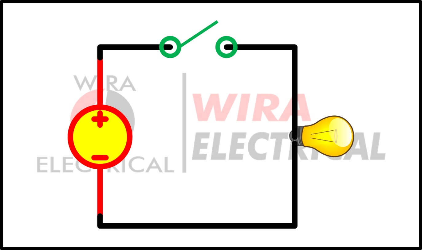
But keep in mind that not every open circuit is an accident. Sometimes we intently make the circuit have an open path. The most common example of this purpose is a switch to turn off a lamp.
Since the switch is open, our circuit does not have a closed path, hence no electrical current is flowing to the lamp.
For our study here, we will use a DC circuit for easier explanation.
For better understanding, observe the circuit below.
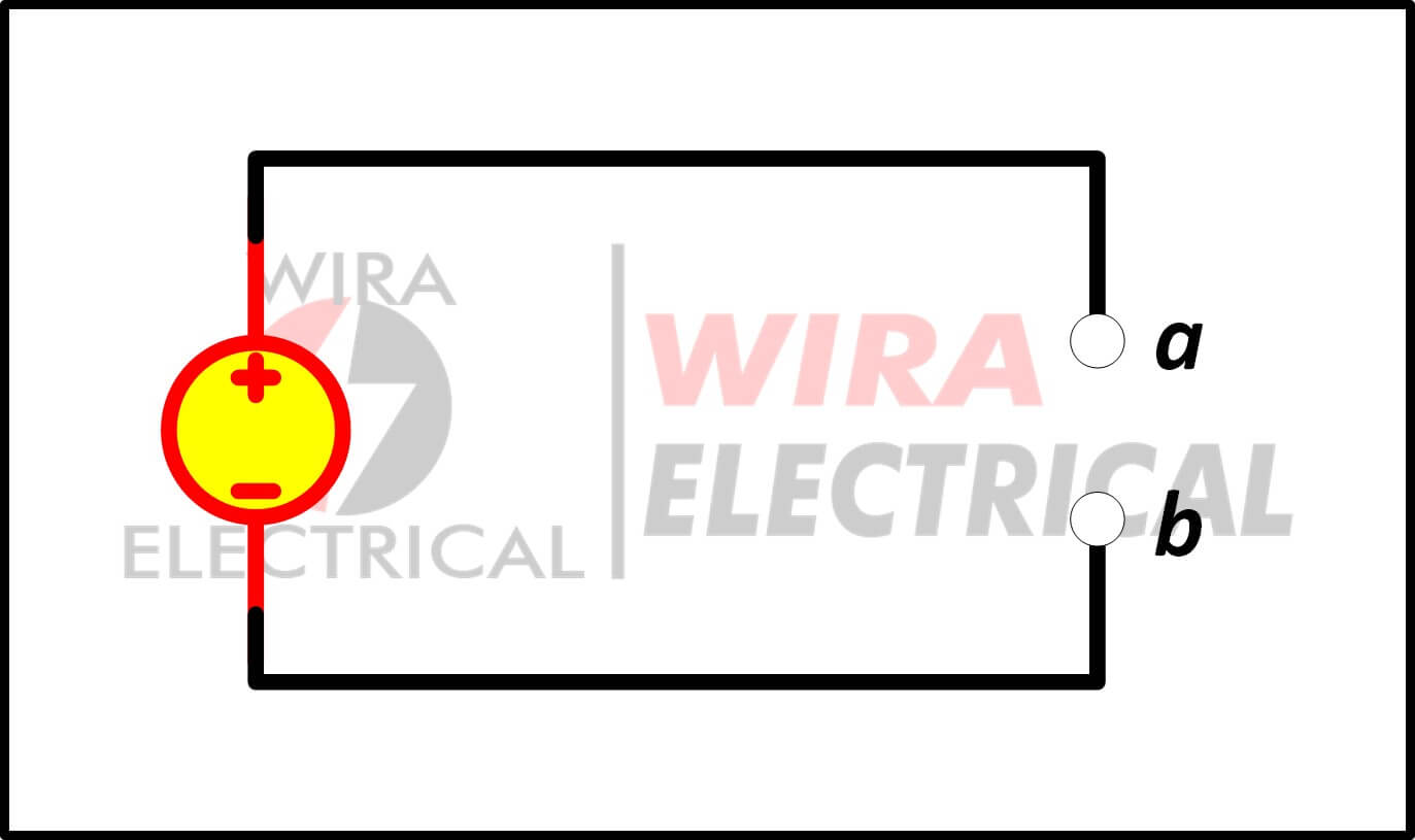
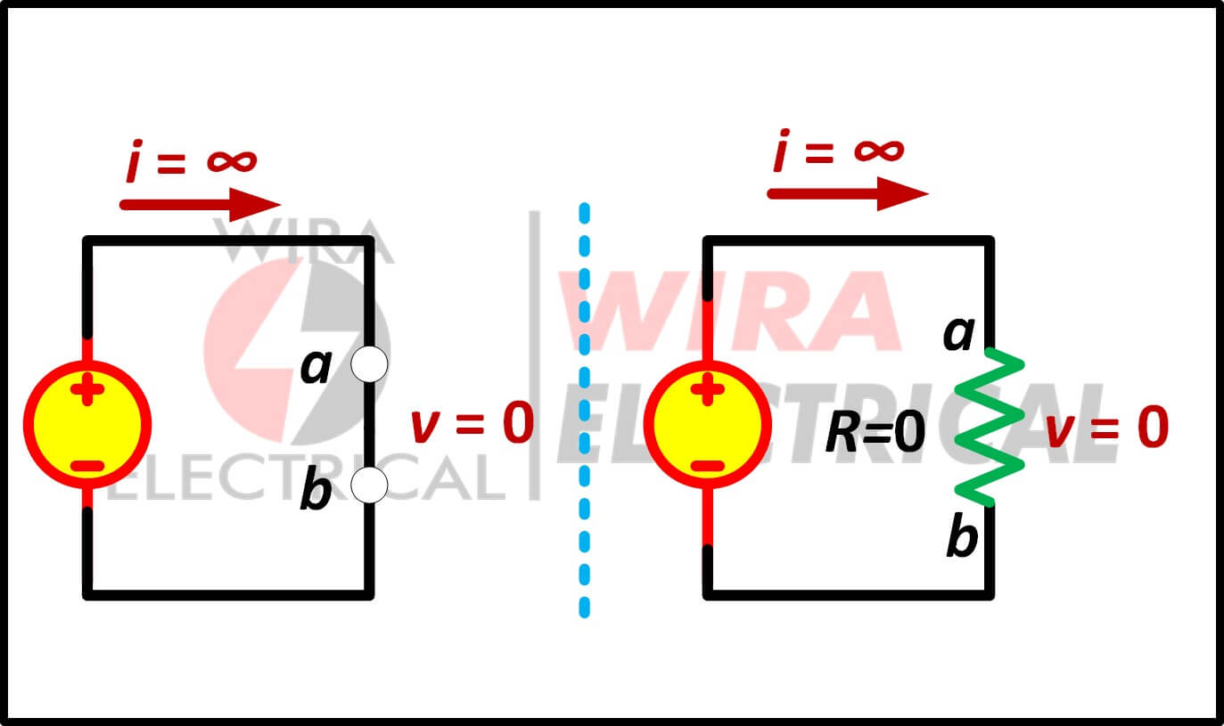
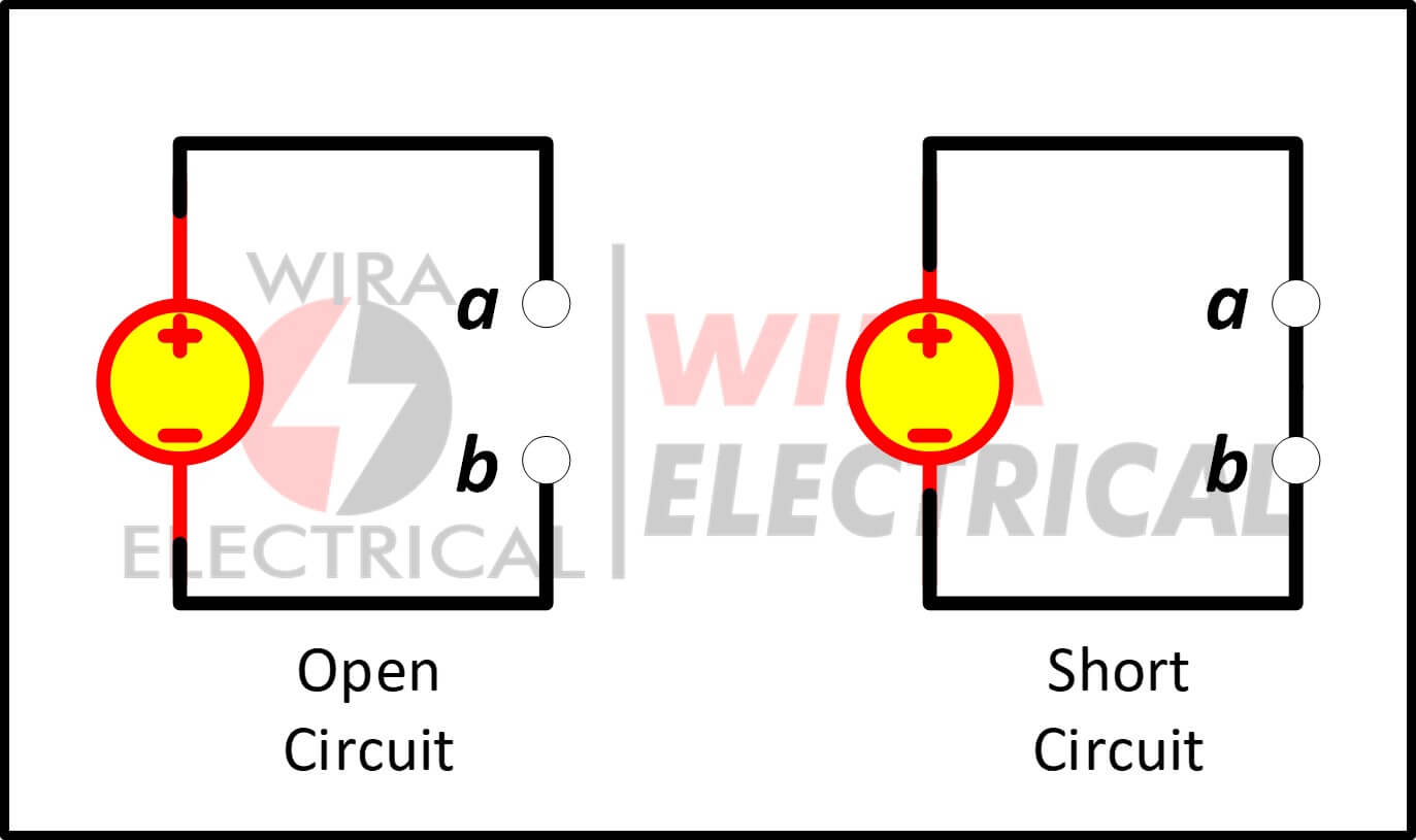
Here we have a circuit with a two-points terminal, a and b.
The open circuit is the pair of terminals that are externally disconnected from each other. Because they are not connected, there is no electrical current flowing through them.
Compared with a “normal” circuit on the right.
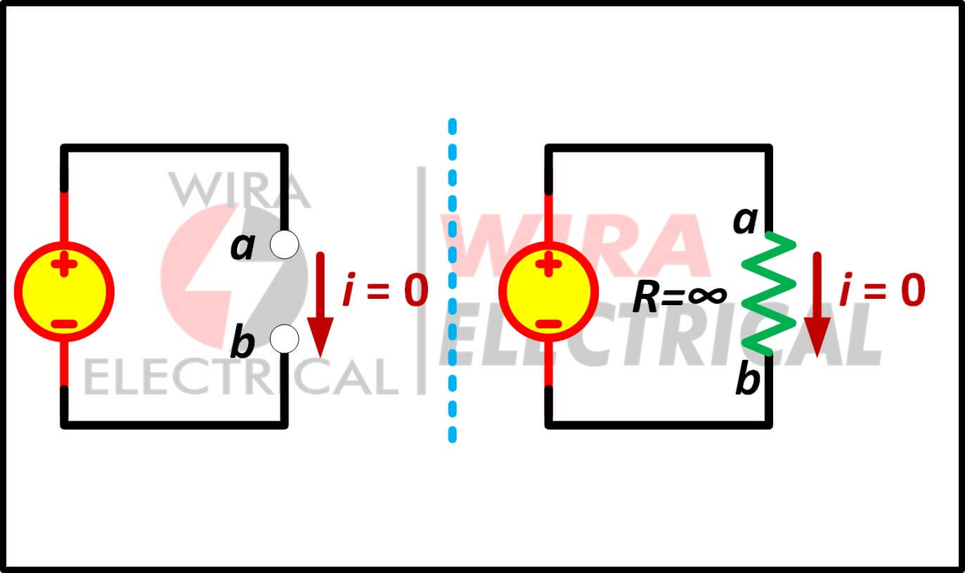
The circuits above show us the open circuit resistance. An open circuit voltage is the voltage measured across a pair of terminals when there is no electrical current flowing through them. In this path, there is no electric current drawn from the source.
We can use Ohm’s Law to make this easier.
\( R = \frac{V}{I} \)
Since there is no electric current, we put \( I = 0 A \), thus
\( R = \frac{V}{0} = \infty\)
It is the same if we do the opposite
\( I = \frac{V}{R} \)
Where \( R = \infty \) thus
\( I = \frac{V}{\infty} = 0 \)
What conclusion can we get from this simple calculation?
We can conclude that an open circuit will not cause any injury or serious problem since there is no electrical current to harm its surroundings. The only thing we must take caution is not to accidentally connect these open terminals with anything, especially our body parts.
Even if there is no electric current flowing through the open terminals, the voltage still exists, up to the maximum voltage supplied by the source.
But an open terminal does not always mean that our electrical circuit will turn off. It depends on our circuit configuration to make it functional even if we intentionally or not, make a hole in our circuit path.
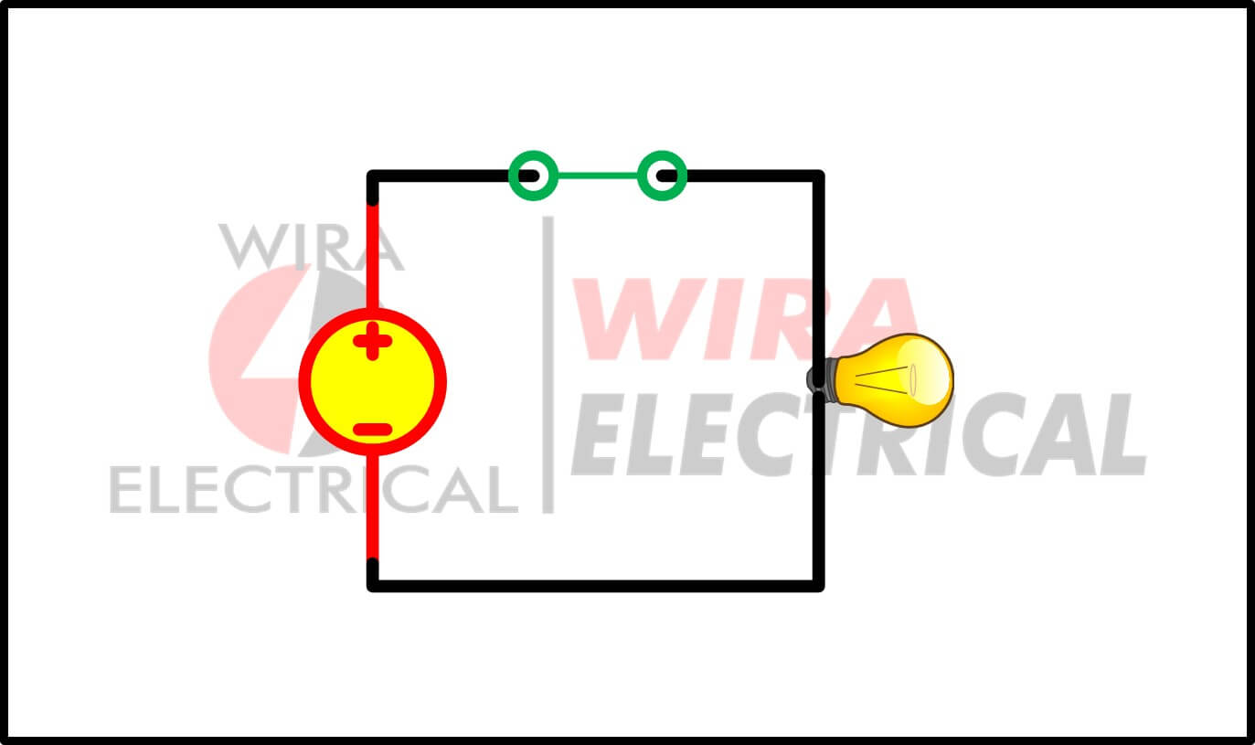
In a series circuit, an open terminal will make the electric current unable to flow through the circuit. As an example, imagine a flashlight circuit which is easily made by a battery, a switch, and a light, all connected in series.
Once the switch is open, the electric current is cut off, the lamp does not glow.
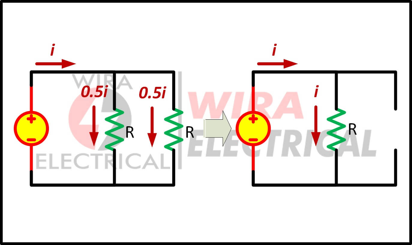
What about an open parallel circuit?
When a parallel circuit has an open terminal on one of its branches, the electric current will flow to another closed circuit branch. Of course, the consequence is the closed circuit branches will have higher current flowing through them.
What About a Short Circuit?
What does a closed look like?
The opposite of an open circuit is a closed circuit. A closed circuit is a circuit where there is no disconnected point, disconnected terminal, or broken path.
Both short circuit and closed circuit share the same principle. So what is the difference between short circuit and closed circuit?
A short circuit is a closed circuit where there is no load in that circuit.
When we are talking about no load, it means our circuit only has a source with a closed path conductor, connecting the positive polarity of a source to its negative polarity directly.
Use an open circuit below to make it easier to imagine a closed circuit.
Short Circuit Meaning in Electricity
A short circuit happens when two points with different potentials get connected with almost no resistance in between. The moment that happens, current spikes as high as the system will allow.
That’s when fuses blow, wires heat up, and breakers snap open.
A short circuit is a pair of terminals that are externally connected to each other. Because they are connected directly only with a conductor wire then there is zero voltage across them.
Why is the resistance zero? A short circuit current is a current flow through a pair of terminals with zero voltage difference
In an ideal condition, a short circuit has exactly zero resistance since there is no load installed in the circuit.
But in the real circuit, it still has very low resistance from the conductor wire.
For now, let us use the ideal condition. Assume that \( R = 0 \), then
\( I = \frac{V}{R} = \frac{V}{0} = \infty \)
What can a short circuit cause?
Short circuits cause high current flowing in the circuit and may damage it. Not only that, if it has a high voltage source then it will produce a large amount of electric power or heat or even a fire. Our electrical devices can be broken and any conductor wires can be melted.
Keep in mind that in the practical field, a conductor wire has non-zero resistance. It can be very low resistance but not exactly zero.
What if we have a short circuit in a series circuit?
A short series circuit is not different with a closed switch. It will act as a conductor wire to carry electrical currents.
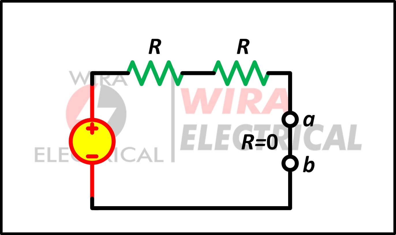
What if we have a short circuit in a parallel circuit?
Opposite from the short series circuit, a short parallel circuit means we put a conductor wire in a parallel connection in the circuit.
Remember that current will likely choose a path with the least resistance as its flowing path. The lower the resistance in a branch, the more current will flow through that branch.
If we use an ideal short circuit then the resistance on that branch will be zero and the current will be infinite.
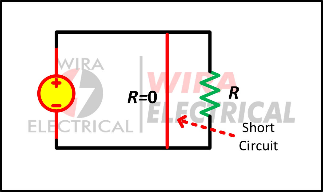
The equivalent resistance the circuit above is
$$
\begin{aligned}
R_{eq} &= \frac{R_1 \times R_2}{R_1 + R_2}\\
&= \frac{0 \times R}{0 + R} \\
&=0
\end{aligned}
$$
Why It’s So Dangerous
Short circuits make things happen fast:
- Current rises far beyond the rated levels
- Components heat up in seconds
- Insulation can fail or burn
- Protective devices must act immediately
This is why standards like IEC 60364 and NEC require proper short‑circuit protection — the margin for error is tiny.
Simple Comparison: Open Circuit vs Short Circuit
Here’s an easy table to refresh the core difference:
Condition | Current Flow | Voltage at Load | Typical Result | Danger Level |
Open Circuit | Nearly zero | Matches supply voltage | Device doesn’t operate | Low |
Short Circuit | Extremely high | Close to zero | Trips protection or causes damage | High |
Both stop a system from working, but one stops it quietly while the other makes itself known.
An open circuit is a disruption in electrical current flow since it prevents it from flowing through the circuit while an open circuit is a huge electrical current flowing through a near zero resistance circuit path.
Both open circuit and short circuit can be considered as circuit failures. But two of them have different characteristics.
In an open circuit, the current flowing in the circuit is zero. On the other hand, in a closed circuit, the current flowing in the circuit is very high (infinite).
The resistance in an open circuit is very high (infinite), while a short circuit has very low resistance (zero).
The voltage drop across the open circuit terminal is equal to the voltage source. Across the short circuit terminal, the voltage drop is zero since the resistance is zero.
The summary between open and short circuit can be observed from the figures below.
Even though these two are considered harmful, we can make use of these extreme conditions to make something.
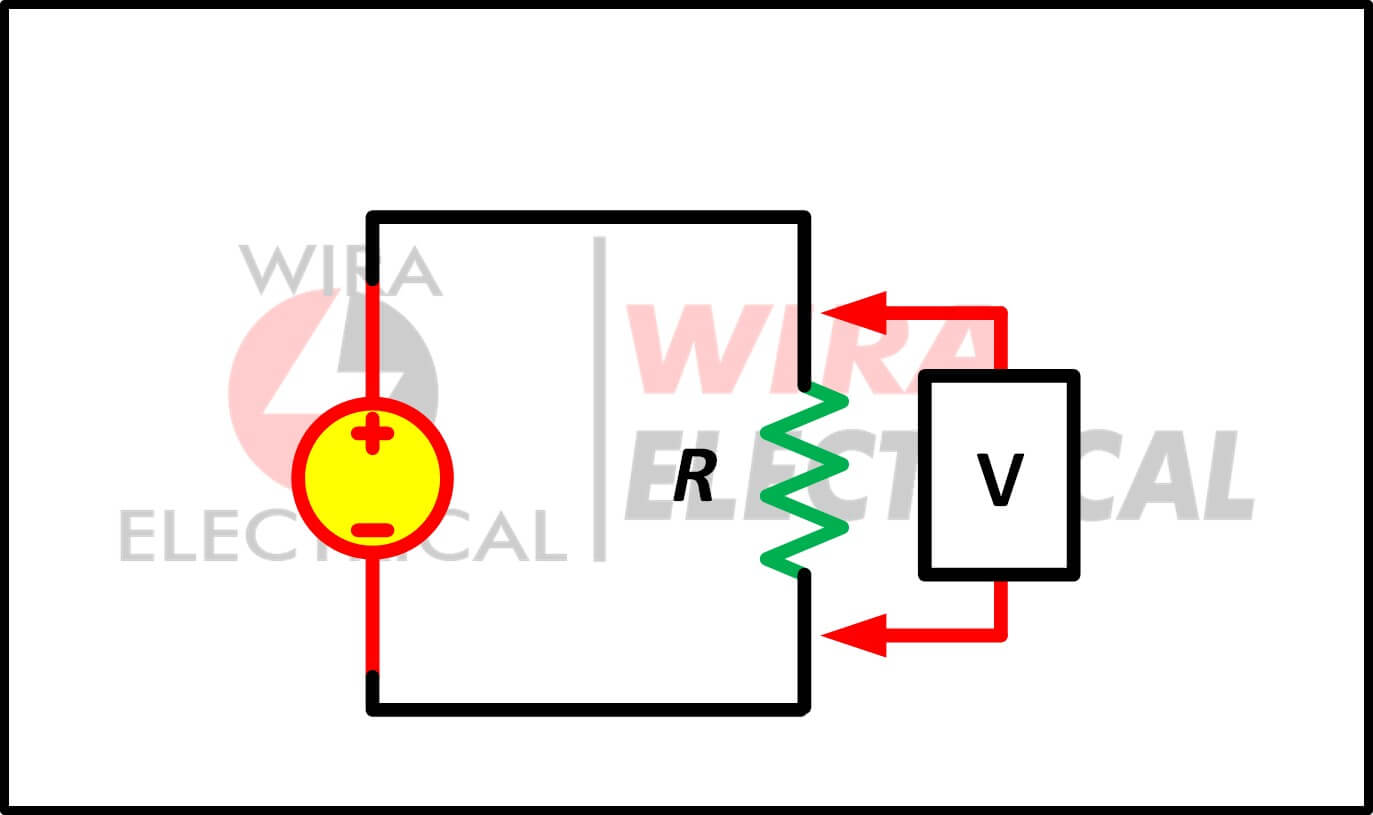
An ideal voltmeter is an open circuit which has very large resistance (not infinite).
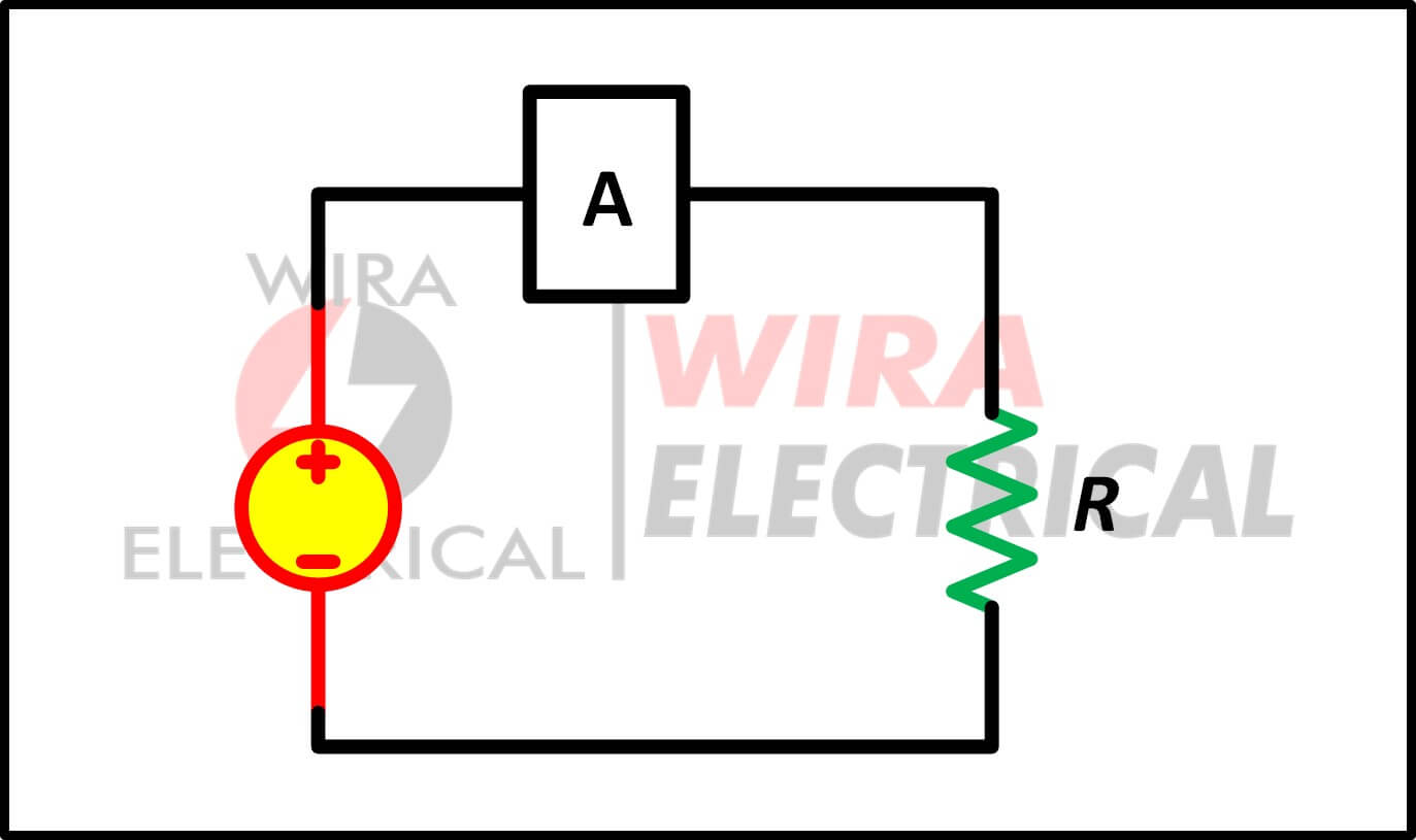
An ideal ammeter is a closed circuit which has very low resistance (not zero).
The Formulas Behind Each Condition
Open Circuit
No current flows, so things become very straightforward:
\( I=0 \)
Most of the supply voltage appears across the break.
Short Circuit
Here’s where calculations matter. Short‑circuit current depends on the total impedance of the source and wiring.
\( I_{sc} = \frac{V}{Z_{source} + Z_{line}} \)
Even small changes in impedance can dramatically alter the fault current, which is why engineers perform careful short‑circuit studies.
How to Tell Whether It’s an Open or Short Circuit
You don’t need fancy equipment — a multimeter and a bit of patience usually solve the mystery.
Detecting an Open Circuit
- Continuity test shows infinite resistance or “OL”
- Voltage appears at the load but nothing responds
- Flexing wires sometimes makes the device work briefly
- No heat, no sparks — just silence
Detecting a Short Circuit
- Very low resistance on continuity test
- Breakers or fuses trip instantly
- Components or conductors may feel warm
- Visual inspection can reveal solder bridges or damaged insulation
Real Examples You’ll Actually See
Open Circuit Examples (Electronics)
- Hairline PCB trace cracks after repeated heating
- Battery terminals corroded just enough to lose contact
- Loose connectors on hobby boards
- Mechanical switches that wear out internally
Short Circuit Examples (Electronics)
- A stray solder blob between SMD pads
- Pinched cables where insulation gets cut
- Miswired connectors between modules
- Small bits of conductive debris landing on a PCB
Pros and Cons (From a Designer’s Perspective)
Aspect | Open Circuit | Short Circuit |
Daily Risk | Low | High |
Detectability | Sometimes tricky | Usually obvious |
System Reaction | Nothing works | Protection activates instantly |
Damage Potential | Low | Very high |
Practical Tips and Avoidable Mistakes
Tips That Actually Help
- Add strain relief so cables don’t fail from movement
- Clean PCBs thoroughly after soldering
- Don’t rush when plugging connectors — alignment matters
- Choose proper fuses or breakers based on real fault currents
Mistakes to Watch Out For
- Assuming a voltage reading means the circuit is fine
- Using oversized fuses that won’t clear faults
- Ignoring slight warmth in cables
- Reworking a PCB without checking for accidental bridges
Summary
An open circuit means a break in our electrical path, there is no electric current flowing through it.
An open circuit has infinite resistance and no electrical current.
A short circuit means a very low resistance path that can produce abnormally high current to flow in our circuit. The lowest resistance path is the shortcut used by the electric current to flow.
A short circuit has near-zero resistance and high electrical current flow.
Key differences:
- Electrical current flow : no electrical current to flow in an open circuit, while a huge electrical current will flow in a short circuit.
- Resistance : an open circuit has infinite resistance, while a short circuit has near zero resistance.
- Cause : open circuit can be caused by broken component, connection, wire, or open switch. A short circuit can be caused by broken insulation
- Example : an open circuit is a flashlight circuit turned off by opening the switch. A short circuit is a frayed electrical cord where exposed wires touch.
FAQ
Why does an open circuit still show voltage?
Because voltage is present, but the loop isn’t closed, so no current flows.
What makes short circuits spark?
The sudden surge of current can ionize air and jump across small gaps.
Does a blown fuse always mean a short?
Not always — a severe overload can also cause it.
References
- IEC 60364 Low-voltage electrical installations
- IEEE Std 141 (Red Book)
- NEC (NFPA 70) Articles 110 and 240
- Horowitz & Hill, The Art of Electronics


It was amazing leaning with you guys
It was amazing lean with you guys