Electronic Filters Explained: Types, Applications, and Design Principles You Can Actually Use
If you’ve ever turned a noisy signal into a clean, stable one—or wondered how your phone tunes into a single frequency without chaos from nearby stations—you’ve already met the unsung hero of electronics: the electronic filter.
It’s one of those topics every engineer bumps into, but few truly feel comfortable with.
The good news? Once you see how filters think—yes, they “think” in frequencies—it all starts to click. You’ll begin spotting them in everything: amplifiers, motor drives, even your home’s power supply.
Let’s unpack what they really do, why they matter, and how you can design one that behaves exactly the way you expect.
What Is an Electronic Filter?
An electronic filter is simply a circuit that lets some frequencies through and holds others back.
Think of it like a bouncer at a club—only certain frequencies get past the door.
The idea may sound simple, but it’s powerful. By arranging resistors, capacitors, and inductors in clever ways, you can “shape” signals to highlight what you want and suppress what you don’t.
The Core Principle
Electronic filters work because components react differently to frequency:
- Capacitors resist low-frequency signals but let higher ones slide through.
- Inductors do the reverse—blocking highs, welcoming lows.
Mix them together, and you get an elegant frequency selector.
According to IEC 60050 and IEEE Std 100, a filter is a network that transmits signals within a specified frequency band while rejecting signals outside it.
That definition underpins nearly every standard you’ll find in IEC 61000 and CISPR EMC guidelines.
We will very depend on the filter circuit if we are designing an audio system where a noise can disturb our audio output. A certain range of frequencies need to be taken out from our circuit for our desired sound quality and better power consumption.
Types of Electronic Filters and Their Applications
Electronic filters are a device for signal processing and filtering in the form of an electrical circuit. This circuit uses components and connects them into specific configurations for specific purposes. After they are interconnected, they are considered as a single device and can be analyzed.
You’ll usually hear about four main kinds of filters, each with its own personality.
Filter Type | What It Passes | Typical Applications |
Low-Pass (LPF) | Frequencies below the cutoff | Power-supply smoothing, audio tone shaping |
High-Pass (HPF) | Frequencies above the cutoff | Removing DC offsets, vibration sensing |
Band-Pass (BPF) | A selected frequency range | Radio tuning, biomedical signals |
Band-Stop (Notch) | All but a narrow frequency band | Eliminating 50/60 Hz hum, interference rejection |
If you picture frequency as a road, each filter is a different kind of traffic control—LPFs let the slow cars roll, HPFs favor the fast ones, and BPFs create a private lane for a chosen speed range.
The most basic electronic filter is a filter RC circuit. Filter RC circuits can act as a low pass filter or high pass filter.
The terms of low and high frequencies do not have specific values prior to designing a circuit. The real value of low and high frequencies are determined by our “how to design a filter circuit”. With a lot of circuit elements along with their values, we can control to pass or to block the desired and undesired frequency.
Our only job when designing an electrical filter is to determine the cut-off frequency first and move to the circuit design along with its circuit analysis to make sure everything is on the track.
Just like circuit elements where you can find active and passive elements, electronic filters also have active filters and passive filters.
Let us learn about four primary types of electronic filter briefly. We have provided the detailed explanation in other lessons.
Low Pass Filter
Low pass filter is an electronic filter which blocks frequencies higher than the cut-off frequency. This filter permits any signals that have lower than cut-off frequency. This circuit will help us to make sure high frequency noise is eliminated.

High Pass Filter
Opposite to the low pass filter, a high pass filter is an electronic filter that eliminates lower frequencies than the cut-off frequency and permits the higher frequency. It is commonly used to make sure the undesired DC voltage offset caused by low frequency components are not disturbing the output.
There are obvious differences on low pass vs high pass filters, just like band pass vs band stop filters.

Band Pass Filter
Band pass filter, as its name implies, permits a certain range of frequency to pass while blocking the other. This electronic circuit has two cut-off frequencies, one for the lower range and one for the higher range.

Band Stop Filter
Opposite to the band pass filter, a band stop filter or notch filter is an electrical filter that blocks a certain range of frequency while passing the rest. Same as the band pass filter, this filter also has two cut-off frequencies at lower and higher range.

Active vs. Passive Electronic Filters
Not all filters are built alike. Some are simple and self-contained; others use active devices that add gain and control.
Just as their name implies, an active filter is basically a filter built by active components such as an operational amplifier along with passive components such as resistor and capacitor to make it work properly.
On the other hand, a passive filter is built purely by passive components such as resistor, inductor and capacitor. A passive filter is very tricky to make since we need to calculate the values of resistors, inductors, and capacitors to make it filter the frequency nicely.
A passive filter will have a hard time on filtering very low frequency since we need a large inductance and capacitance, as it has limitations on lower end frequency. The very broad high frequency is caused by the parasitic inductances and capacitances.
This is why we need to be careful when designing a passive filter.
Not too much difficulty compared to the passive filter, an active filter utilizes active components such as an operational amplifier along with resistors and capacitors. This type of filter is very capable of processing low-range frequencies (near to 0 Hz) unlike passive filter
Not only that, since it utilizes operational amplifiers, it is capable of amplifying such as voltage gain. This filter is very versatile to be used for high-order filters but less efficient on dealing with very high-range frequencies since every operational amplifier has their own limitations, their op-amp has bandwidth limitation.
Aspect | Passive Filter | Active Filter |
Core parts | R, L, C only | Op-amps, transistors, or ICs |
Signal gain | Always ≤ 1 | Can amplify |
Power need | None | Requires DC supply |
Frequency range | Up to hundreds kHz | Up to MHz (limited by op-amp) |
Impedance interaction | Can load next stage | Buffering possible |
Best for | Power and EMI circuits | Audio, instrumentation, control systems |
In practice, passive filters are sturdy and predictable—great for high-voltage or power circuits.
Active filters shine when you need fine control or compact size. It’s why audio engineers swear by op-amp filters for tone control.
Analog vs. Digital Electronic Filters
Here’s where things get interesting. Today, filtering isn’t just about components; it’s also about code.
Type | Built With | Flexibility | Latency |
Analog Filter | R, L, C, op-amps | Hardware-fixed | Negligible |
Digital Filter | Microcontroller or DSP | Reprogrammable | Some delay |
Analog filters work in real time and never miss a beat—perfect for front-end conditioning before an ADC.
Digital filters, on the other hand, are like chameleons: reconfigurable, precise, but a bit slower. In modern systems, engineers often use both—an analog stage first, then a digital fine-tune afterward.
How Electronic Filters Work
At their core, filters manipulate impedance to sculpt frequency response.
Let’s start with the simplest one you can build on a breadboard—the RC low-pass filter.
RC Low-Pass Filter Basics
Circuit layout:
A resistor \( R \) in series with a capacitor \( C \) connected to ground.
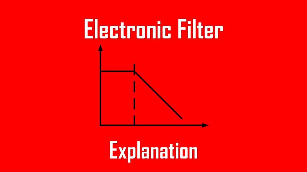
Cutoff frequency:
\( f_C = \frac{1}{2\pi R C} \)
At \( f_c \), the output voltage is about 70 % of the input (−3 dB).
Behavior summary:
- At low frequencies, the capacitor acts almost open; the signal passes easily.
- At high frequencies, the capacitor becomes a shortcut to ground; highs disappear.
That’s the core of how an electronic filter works—by leveraging frequency-dependent impedance.
Just as stated before, an electronic filter is one type of circuit that is able to block a specific range of frequency and/or pass specific ranges of frequency. Not only block and pass, it is also able to amplify the passing range of frequency.
This type of circuit is very helpful for:
- DC power supplies: an electronic filter is able to block (or eliminate) specific ranges of frequency (mainly a high frequency which is considered as a noise), to act as a circuit to reduce ripple. If you build a DC power supply from an AC input, you might want to consider using a filter to smoothen your output.
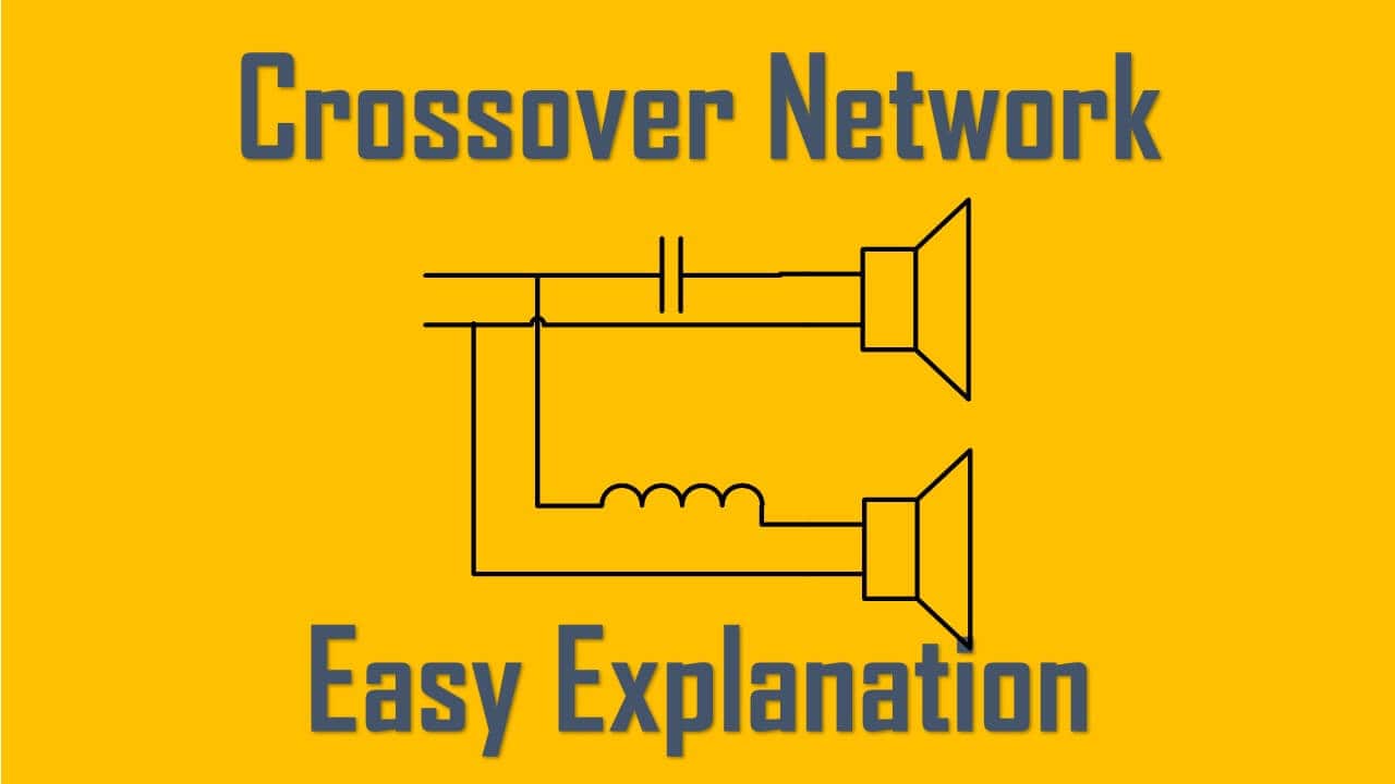
- Audio system: crossover network is used to selectively pass a specific range of frequency to the corresponding audio devices. For example, pass the low-range frequency to woofer, mid-range frequency to speaker, and high-range frequency to tweeter.
- Communication system: a communication system such as radio can receive a specific frequency due to the electronic filter circuit. The desired frequency is captured while undesired frequencies are rejected.
- Analog to Digital Converter (ADC): electronic filter is a great help for Analog to Digital Converter to remove noise and interference from signal input and protect the circuit.
Step-by-Step: Designing a Simple RC Filter Circuit
Let’s say you want to filter noise above 1 kHz from a signal line.
- Pick a resistor value.
R=10kΩR = 10 k\OmegaR=10kΩ keeps current modest. - Solve for capacitance.
$$
\begin{aligned}
C &= \frac{1}{2\pi R f_C} = \frac{1}{2\pi (10000)(1000)}\\
& = 15.9 nF
\end{aligned}
$$ - Choose a standard part.
The nearest is 16 nF. Easy to find. - Wire it up and test.
Feed in a sine wave and watch an oscilloscope—above 1 kHz the output drops. - Adjust if needed.
Small tweaks to R or C will shift the cutoff.
That’s all it takes to craft a basic low-pass. Once you’ve done one, designing others—high-pass, band-pass, notch—feels like rearranging puzzle pieces.
Band-Pass and Band-Stop Filter Fundamentals
Moving up a notch (pun intended), we get filters that isolate or reject specific bands.
Band-Pass Filter (BPF)
Passes frequencies between \( f_1 \) and \( f_2 \).
$$
\begin{aligned}
f_0 &= \sqrt{f_1 f_2}\\
BW &= f_2 – f_1\\
Q &= \frac{f_0}{BW}
\end{aligned}
$$
A higher Q gives a sharper, more selective curve.
In radio design, engineers often chase Q values above 10 to isolate narrow channels.
Band-Stop (Notch) Filter
The opposite—everything passes except a narrow band.
A 50 Hz or 60 Hz notch is common in medical ECG amplifiers, silencing mains hum without touching heart-signal frequencies.
Where You’ll Find Electronic Filters
Once you start looking, they’re everywhere.
1. Consumer Electronics
- Audio equalizers, headphone amplifiers
- Smartphone RF stages
- Power-supply decoupling networks
2. Industrial Automation
- PLC sensor inputs
- Motor-drive feedback loops
- EMI compliance per IEC 61000-6-4
3. Power and Energy Systems
- LCL filters for inverters (IEC 61000-3-2)
- Harmonic suppression in converters
- Reactive compensation filter banks
4. Medical and Scientific Devices
- ECG/EEG amplifiers with band-pass windows
- Optical sensors with notch filters for ambient light
Each use case demands a slightly different balance of simplicity, precision, and ruggedness.
Advantages and Disadvantages
Advantages | Disadvantages |
Cleaner signals and higher SNR | Possible phase shift or delay |
Protects sensitive circuits | Can attenuate wanted harmonics |
Simple RC/RL topologies | Tolerances affect precision |
Active types add gain | Need power supply |
Digital versions are reconfigurable | Require computing resources |
Like any design, filtering is a trade-off. The trick is deciding which imperfection you can live with.
Tips, Best Practices, and Common Mistakes
Best Practices
- Simulate before soldering.
Tools like LTspice or Multisim can save hours of rework. - Account for tolerance.
A 10 % cap variation shifts the cutoff more than you’d think. - Watch impedance.
Mismatch between filter and next stage can warp response. - Mind op-amp specs.
Slew rate and bandwidth define your real limits. - Follow EMC standards.
Check IEC 61000-4-7 and CISPR 16-1-1 when designing suppression networks.
Common Mistakes
- Using inductors on high-frequency PCBs without shielding—invites EMI
- Ignoring op-amp bandwidth, causing unexpected roll-off.
- Forgetting load effects—real circuits rarely match the simulator’s infinite impedance.
Every experienced designer has learned one of these the hard way.
Conclusion
Electronic filters don’t just clean signals—they shape how systems behave.
From the buzz-free sound in your headphones to the quiet hum of an inverter, filters keep the chaos of the real world in check.
Once you understand what happens at that magical −3 dB point and how components react to frequency, you gain real control. You’ll start designing circuits that listen only to what matters.
So go ahead—build that RC filter, watch the curve drop on your scope, and realize you’ve just tamed a piece of the frequency spectrum.
And if you’ve read this far, you’re already thinking like a practicing engineer.
FAQ: Electronic Filters
Q1: What’s the main difference between low-pass and high-pass filters
Low-pass lets slow changes through and blocks fast ones; high-pass does the opposite by swapping resistor and capacitor positions.
Q2: What’s the cutoff frequency again?
It’s where output voltage falls to 70.7 % (−3 dB) of input—the point dividing “mostly passed” from “mostly blocked.”
Q3: Are digital filters better than analog ones?
Not automatically. Digital filters are flexible and precise, but analog filters react instantly and don’t need processing power.
Q4: What does the Q factor mean?
It’s a measure of selectivity—high Q equals narrow bandwidth and stronger resonance.
Q5: Can you chain filters together?
Yes. Designers often cascade low-pass and band-pass stages to sculpt more complex responses.
References
- IEC 60050 – International Electrotechnical Vocabulary, Chapter 161
- IEC 61000 series – Electromagnetic compatibility standards
- IEEE Std 100-2000 – Dictionary of Electrical and Electronics Terms
- Sedra & Smith, Microelectronic Circuits, 8th Ed., Oxford University Press
- Hayt & Kemmerly, Engineering Circuit Analysis, McGraw-Hill
- Horowitz & Hill, The Art of Electronics, Cambridge University Press