Filter Capacitor | C Filter Electronic Circuits
A filter capacitor is a capacitor that removes a specific frequency or frequency range from a circuit.
Very low frequency signals are usually filtered out using capacitors. These are signals with a frequency value very near to 0Hz. DC signals are another name for these.
Because the capacitor impedance is a function of frequency, it is employed in analog electronic filters as a reactive component. The frequency of the capacitor that impacts a signal can vary.
As a result, this feature is commonly exploited in filter design.
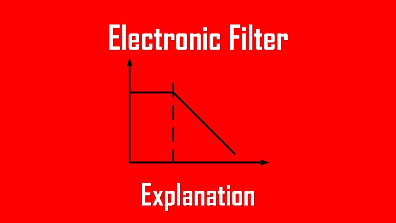
LPF analog electronic filters can be employed to carry out a preset signal processing function. This filter’s primary function is to allow low frequencies while blocking high frequencies.
An HPF, on the other hand, admits high frequencies while blocking low frequencies. Analog components such as resistors, capacitors, transistors, op-amps, and inductors can be used to create an electrical filter.
The filter capacitor and how it works are discussed in this article.
Filter Capacitor Introduction
Because capacitors are reactive elements, they can be used in analog electronic filters. The reason for this is that, as mentioned in the article about impedance and reactance, a capacitor’s impedance is a function of frequency.
This means that a capacitor’s effect on a signal is frequency-dependent, which is a useful trait in filter construction.
To accomplish a predefined signal processing function, analog electronic filters are utilized.
A low-pass filter (LPF) is an example of such a function that allows low frequencies to pass while blocking high frequencies.
Another example is a high-pass filter (HPF), which allows high frequencies to pass through while blocking low frequencies.
These are some of the most basic filter types that can be combined to produce more complex filters like band-pass or notch filters.
Electronic filters can be made in a variety of methods. Capacitors, inductors, resistors, transistors, and operational amplifiers are all analog components that can be used to make them.
They can also be implemented using digital technology, which consists of digital signal processing circuits consisting of a specialized computer or microcontroller and application-specific software.
Passive and active analog filters are the two types of analog filters. Passive filters only use resistors, inductors, and capacitors, while active filters use amplifying circuits and components like transistors and op amps.
Passive filters have the advantage of requiring no power source other than the processed signal, but active filters have the advantage of being smaller and less expensive.
Filter Capacitor Functions
In the power rectifier circuit, the filter capacitor is utilized to filter out AC components and make the output DC smoother. To improve the operating effect of the filter capacitor in precision circuits, a combination of parallel capacitor circuits is frequently utilized at this time.

The low-frequency filter capacitor is mostly used for mains power supply filtering or filtering after transformer rectification, and its working frequency is the same as the mains power for 50Hz.
The high-frequency filter capacitor is mostly used for filtering after the switching power supply has been rectified, and its operating frequency ranges from a few thousand to tens of thousands of Hz. In the switching power supply, the filter capacitor is extremely critical.
The correct selection of filter capacitors, particularly the output filter capacitor, is a subject that all engineering and technical staff are worried about.
Electrolytic capacitors that are commonly utilized in 50 Hz power frequency circuits. The charging and discharging times are in the range of milliseconds, and the pulsating voltage frequency is only 100 Hz.
The needed capacitance to get a lower ripple coefficient can be hundreds of thousands of microfarads. As a result, the capacitance of standard low-frequency aluminum electrolytic capacitors is increased.
The capacitor’s capacitance, loss tangent value, and leakage current are the major metrics used to determine its benefits and drawbacks. The switching power supply’s output filter electrolytic capacitor has a sawtooth voltage frequency in the tens of thousands of hertz, if not tens of megahertz.
Capacitance is not the primary indicator at this time.
The “impedance-frequency” characteristic is used to assess the quality of high-frequency aluminum electrolytic capacitors. It must have a reduced equivalent impedance within the switching power supply’s operating frequency while also having an effective filtering impact on the high-frequency spikes created when the semiconductor device is functioning.
Ordinary low-frequency electrolytic capacitors become inductive about 10,000 Hz, making them unsuitable for switching power supplies. There are four terminals on the particular high-frequency aluminum electrolytic capacitor for switching power supply.
The positive electrode of the capacitor is led out from both ends of the positive aluminum sheet, while the negative electrode is led out from both ends of the negative aluminum sheet.
The current enters from one positive terminal of the four-terminal capacitor, passes through the capacitor, and then flows from the other positive terminal to the load; the current leaving the load enters from one negative terminal of the capacitor, passes through the capacitor, and then flows from the other negative terminal to the power supply’s negative terminal.
Read also : transformer power distribution system
What Are Filter Capacitor and How Do They Work?
The principle of capacitive reactance governs how filter capacitors function. Capacitive reactance describes how a capacitor’s impedance (or resistance) changes when the frequency of the signal traveling through it changes.
Resistors are passive components. This indicates that regardless of the frequency of a signal, resistors provide the same resistance. This means that a 1Hz signal and a 100 KHZ signal will both flow through a resistor with the same resistance.
Frequency isn’t a consideration.
A capacitor, on the other hand, is not like this. A reactive device is a capacitor. The frequency of the signal coming through will change the resistance, or impedance, of the device.
According to the formula XC=1/2πfc, capacitors are reactive devices that offer stronger resistance to lower frequency signals and reduced resistance to higher frequency signals.
Because different frequency signals have varying impedance values, a capacitor can be used as a resistor in a circuit. We’ll show you how to do it using real circuits down below.
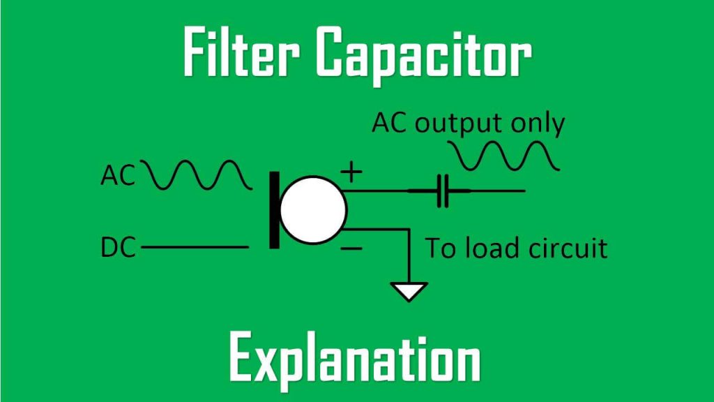
Filter Capacitor: Block DC and Pass AC
Because capacitors have a very high low frequency resistance and a very low high frequency resistance, they act as a high pass filter, which allows high frequency signals to pass while blocking low frequency signals.
Many times in a circuit, both DC and AC signals must be used, at least at some point in the circuit. However, we may only want AC signals and the DC removed at a later stage in the circuit.
A microphone circuit is an example of such a circuit. For the microphone to be powered on, we need DC as input, and we need AC as output, which represents the voice signal or music, or whatever else we want the microphone to record.
How can we filter out the signal’s DC component?
To filter out the DC signal, we utilize a capacitor.
This is accomplished by connecting the capacitors in series. This is a capacitive high-pass filter in this arrangement, as seen in the circuit below. Signals of a low frequency, or DC, will be blocked.
After a signal that contains both DC and AC signals, a 0.1µF ceramic capacitor, or a value in that range, is usually used. And this capacitor eliminates the DC component, allowing just AC to pass.

Filter Capacitor: Filtering Out AC Signals
Capacitors can act as low-pass filters, passing DC signals while blocking AC, in the same manner that they can act as high-pass filters, passing high frequencies while blocking DC.
Instead of being connected to the component in series, the capacitor will be connected in parallel.

This is a capacitive high-frequency filter. It’s important to remember that current follows the path of least resistance. High frequency signals will pass through the capacitor since it has a low resistance to high frequency impulses.
As a result, the circuit acts as a high frequency filter in this setup. Because the capacitor has too much resistance for low frequency signals, low frequency current signals will not pass through it. Only high-frequency communications are allowed to pass.
Filter Capacitor Characteristics
Low-temperature rise
The harmonic filter loop is made up of a capacitor series reactor that generates the lowest impedance at a certain harmonic order, allowing a significant amount of harmonic current to be absorbed.
The harmonic filter’s stable absorption effect is influenced by the capacitor’s quality. The temperature has a strong influence on the filter’s service life. The shorter the service life, the higher the temperature.
The filter full film capacitor offers low temperature rise properties, extending its service life.
Loss is minimal
The tangent value of dielectric loss (tg): 0.0003.
Safety
The internal single capacitors are provided with protection mechanisms in accordance with GB and IEC requirements. The protective device will act instantly and automatically cut off the power supply to prevent secondary disasters if the circuit or single capacitors are abnormal.
It has a discharge resistor built in to provide electrical safety and maintenance. The outside shell is made of steel stamping, and the inside and outside are coated with weather-resistant high-temperature baking paint, making it extremely safe.
Convenience
Because of its tiny size and low weight, it is exceptionally easy to carry and install.
Filter Capacitor X
An input line has X capacitors attached across it. This topology is depicted in the diagram below:

An X capacitor’s job is to reduce some of the electrical noise generated by the power supply line. The capacitor shorts out high frequencies while allowing lower frequencies to get through.
Because polyester capacitors might overheat, X capacitors typically have a capacitance of 1F to 10F and are built of polypropylene for high frequency applications. Polarized capacitors, such as electrolytic capacitors, can be utilized if the line voltage is DC.
If X capacitors fail, they may cause a safety issue. Capacitors can fail in one of two ways: open-circuit or short-circuit failure.
There is a risk of fire if an X capacitor fails in the short circuit mode unless a circuit breaker reacts by blowing an adequately specified fuse.
The circuit works as if the capacitor isn’t there at all if the failure mode is open-circuit, exposing the appliance to noise. In most cases, no damage is done, but because the filter is inactive, performance loss may occur.
Filter Capacitor Y
Y capacitors are connected between the line and the chassis of the appliance. This topology can be seen in the following schematic:

A Y capacitor serves the same purpose as an X capacitor. When the appliance has a grounded chassis, this topology is employed. The chassis can operate as an electromagnetic shield (Faraday cage) to protect the appliance from RF radiation from the outside world.
This topology is potentially more harmful to the user in the event of a capacitor failure.
Nothing happens if one or both Y capacitors fail in the open-circuit state except the loss of efficient filtering. This may degrade performance, particularly on more sensitive devices, but it will not pose a safety risk.
In the event that one of the Y capacitors fails in the short-circuit mode, the device’s chassis becomes directly linked to the line voltage. There is a risk of electrical shock if the user contacts the chassis.
If both Y capacitors fail at the same time, there is a risk of fire since the line voltage supply will be shorted. The chassis must be securely grounded with a three-prong power connector to avoid these dangers.
The ground wire in the home electrical installation is connected to the third prong on the power cord plug. To avoid fire concerns, the proper fuses must also be placed.
Between 0.001µF and 1µF, Y capacitors can have a wide variety of capacitance values. For Y capacitor applications, metallized paper and film capacitors are preferred over ceramic capacitors due to their stability, higher capacitance values, and self-healing properties, as well as the fact that metallized capacitors’ failure mode is open circuit, whereas ceramic capacitors’ failure mode is short circuit, which is potentially more dangerous to users.
Filter Capacitor Formula
As we’ve seen, the capacitive reactance (Xc) of a capacitor is related to the frequency and capacitance of the capacitor’s input signal.

As a result, the filter capacitor’s capacitive reactance (Xc) is inversely proportional to the signal’s frequency (f).
Filter Capacitor Testing
The filter-capacitor can be checked in two ways:
Make sure the capacitor is entirely depleted before inspecting it.
If the capacitor is not totally discharged, connect it to a load to discharge it. Set your multimeter to read high ohm range if you’re using one. Connect the multimeter to the capacitor’s positive and negative ends correctly.
If the meter starts at 0 and moves to infinity, the capacitor is in good working order; if the meter stays at 0, the capacitor is not charging through the meter, indicating that it is not working properly.
Charge it with a DC power supply
Then measure the voltage across the capacitor’s anode and cathode. Just before applying the voltage, the polarity of the capacitor is critical in this test. After charging the capacitor, detach the voltage source from the capacitor and measure the voltage on the capacitor with a multimeter.
When checked, the charged capacitor must maintain the applied voltage. When the multimeter is connected, the voltage will rapidly decrease to zero since the capacitor will be discharging through the multimeter.
If the capacitor does not keep any value near the applied voltage, it is not functioning properly.
Filter Capacitor Applications
The following are some examples of how this can be used.
- The line filter capacitor is used in a variety of industrial loads and appliances to protect the appliance from line voltage noise as well as other devices on the same line from the noise generated within the circuit.
- These capacitors are suitable for use in all forms of signal processing filters. An audio equalization is the best example of this application. It allows for amplification of low, high, and middle frequency tones by using different frequency bands.
- It is used to remove glitches from DC power rails.
- It is used to remove RFI (radio frequency interference) from power and signal lines entering and exiting devices.
- To produce a smooth DC power supply, attach this capacitor after the voltage regulator.
- This capacitor is used in filters for audio, IF, and RF.
Frequently Asked Questions
What does a filter capacitor do ?
The filter capacitor can be used to limit the input signal’s DC component. The AC component of the input signal can also be rejected or bypassed.
Filter capacitors can reduce the bandwidth of a signal or remove a certain frequency spectrum from it. It can also be used to clean up the circuitry by removing unnecessary components or noise.
How to select filter capacitors?
-Cost
-Range of operation
-Size
-Precision
-Stability
-Operating temperature
-Leakage current
What is the effect of a capacitor as a filter?
The capacitor provides a high level of resistance to the low-frequency input signal. The high-frequency signal, on the other hand, has a low resistance, therefore when the capacitor is linked in series with the power signal, only the AC component may flow through.
When the capacitor is connected in parallel to the load, only the DC component can flow through.
What are the advantages and disadvantages of a capacitor filter?
Capacitor-filters have the advantages of being less expensive, smaller in size, and more widely available.
The disadvantages are that it is susceptible to temperature changes and that its capacitance decreases with time.
What happens when the filter capacitor value is larger?
The voltage will be small with a larger filter capacitor. There will be a large time constant. The charge will be sustained for a longer period of time, but it will consume a significant quantity of current, take a long time to complete, and be costly.
Which one is best either capacitor filter or inductor filter?
Inductor fitters are more expensive than capacitor filters. The filter-capacitor size is always smaller than the inductor filter size.
Smoothing voltage is better with the capacitor filter, whereas smoothing current is better with the inductor filter.
Which type of capacitor is used in a low-pass filter?
The working range, temperature, sensitivity, stability, cost, size, and other factors all influence the type of capacitor used in low pass filters. It is possible to utilize the capacitor that meets the specifications.
What is the difference between a rail and a filter capacitor in a circuit?
The noise or ripple in the rail power line is filtered out by a rail capacitor. This capacitor is mostly used to keep the voltage stable and at its rated value.
Where is the filter capacitor used for various purposes such as removing the AC component of the signal, blocking the DC component of the signal, as a bypass filter, EMI filter, limiting the signal’s bandwidth, removing a certain range of the signal, and so on?
Why do we use capacitors as filters in rectification when capacitors are used to block DC and allow AC?
The filter-capacitor is connected in parallel to the load appliances circuit in the rectifier circuit. The AC component of the input signal will pass through the filter capacitor, while the DC component will flow through the load.
In the presence of a high-frequency signal, the capacitor has a low resistance.