Understanding Passive Filters Definition and Examples
The concept of filters has been an integral part of the evolution of electrical engineering from the beginning. Several technological achievements would not have been possible without electrical filters
Because of this prominent role of filters, much effort has been expended on the theory, design, and construction of filters and many articles and books have been written on them.
Passive Filters
Our discussion in this chapter should be considered introductory.
A filter is a circuit that is designed to pass signals with desired frequencies and reject or attenuate others.
As a frequency-selective device, a filter can be used to limit the frequency spectrum of a signal to some specified band of frequencies. Filters are the circuits used in radio and TV receivers to allow us to select one desired signal out of a multitude of broadcast signals in the environment.
A filter is a passive filter if it consists of only passive elements R, L, and C. It is said to be an active filter if it consists of active elements (such as transistors and op-amps) in addition to passive elements R, L, and C.
We consider passive filters in this section and active filters in the next section. Besides the filters we study in these sections, there are other kinds of filters—such as digital filters, electromechanical filters, and microwave filters—which are beyond the level of the text.
As shown in Figure.(1), there are four types of filters whether passive or active:
- A lowpass filter passes low frequencies and stops high frequencies, as shown ideally in Figure.(1a).
- A highpass filter passes high frequencies and rejects low frequencies, as shown ideally in Figure.(1b).
- A bandpass filter passes frequencies within a frequency band and blocks or attenuates frequencies outside the band, as shown ideally in Figure.(1c).
- A bandstop filter passes frequencies outside a frequency band and blocks or attenuates frequencies within the band, as shown ideally in Figure.(1d).

Table.(1) presents a summary of the characteristics of these filters. Be aware that the characteristics in Table.(1) are only valid for first- or second-order filters—but one should not have the impression that only these kinds of filter exist. We now consider typical circuits for realizing
the filters shown in Table.(1).
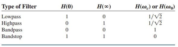
ωc is the cutoff frequency for lowpass and highpass filters; ω0 is the center frequency for bandpass and bandstop filters.
Lowpass Filter
A typical lowpass filter is formed when the output of an RC circuit is taken off the capacitor as shown in Figure.(2).

The transfer function is
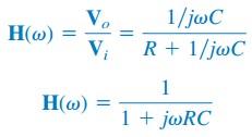
Note that H(0) = 1, H(∞) = 0. Figure.(3) shows the plot of |H(ω)|, along with the ideal characteristic.
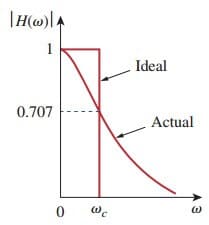
The half-power frequency, which is equivalent to the corner frequency on the Bode plots but in the context of filters is usually known as the cutoff frequency ωc, is obtained by setting the magnitude of H(ω) equal to 1/√2, thus

The cutoff frequency is also called the rolloff frequency.
A lowpass filter is designed to pass only frequencies from dc up to the cutoff frequency ωc
A lowpass filter can also be formed when the output of an RL circuit is taken off the resistor. Of course, there are many other circuits for lowpass filters.
Read also : wien bridge oscillator
High Pass Filter
A highpass filter is formed when the output of an RC circuit is taken off
the resistor as shown in Figure.(4).
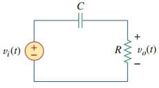
The transfer function is
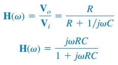
Note that H(0) = 0, H(∞) = 1. Figure.(5) shows the plot of |H(ω)|.
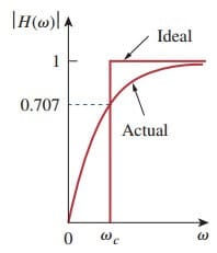
Again, the corner or cutoff frequency is

A highpass filter is designed to pass all frequencies above its cutoff frequency ωc.
A highpass filter can also be formed when the output of an RL circuit is taken off the inductor.
Bandpass Filter
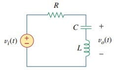
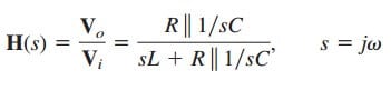
The RLC series resonant circuit provides a bandpass filter when the output is taken off the resistor as shown in Figure.(6).
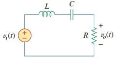
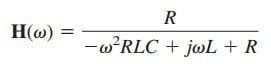
The transfer function is
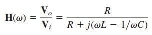
We observe that H(0) = 0, H(∞) = 0. Figure.(7) shows the plot of |H(ω)|.
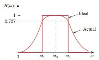
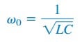
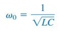
The bandpass filter passes a band of frequencies (ω1 < ω < ω2) centered on ω0, the center frequency, which is given by
A bandpass filter is designed to pass all frequencies within a band of frequencies, ω1 < ω < ω2.
Since the bandpass filter in Figure.(6) is a series resonant circuit, the half-power frequencies, the bandwidth, and the quality factor are determined like before.
A bandpass filter can also be formed by cascading the lowpass filter (where ω2 = ωc) in Figure.(2) with the highpass filter (where ω1 = ωc) in Figure.(4).
Bandstop Filter
A filter that prevents a band of frequencies between two designated values (ω1 and ω2) from passing is variably known as a bandstop, bandreject, or notch filter. A bandstop filter is formed when the output RLC series resonant circuit is taken off the LC series combination as shown in Figure.(8).
The transfer function is

Notice that H(0) = 1, H(∞) = 1. Figure 14.38 shows the plot of |H (ω)|.
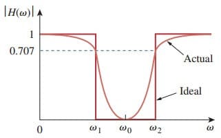
Again, the center frequency is given by
while the half-power frequencies, the bandwidth, and the quality factor are calculated using the formulas in the previous post for a series resonant circuit.
Here, ω0 is called the frequency of rejection, while the corresponding bandwidth (B = ω2 – ω1) is known as the bandwidth of rejection. Thus
A bandstop filter is designed to stop or eliminate all frequencies within
a band of frequencies, ω1 < ω < ω2.
Notice that adding the transfer functions of the bandpass and the bandstop gives unity at any frequency for the same values of R, L, and C.
Of course, this is not true in general but true for the circuits treated here. This is due to the fact that the characteristic of one is the inverse of the other.
Passive Filters Conclusion
In this we can make conclusions that:
- From Equations.(1), (3), (5), and (7), the maximum gain of a passive filter is unity. To generate a gain greater than unity, one should use an active filter.
- There are other ways to get the types of filters treated in this post.
- The filters treated here are the simple types. Many other filters have sharper and complex frequency responses.
Passive Filters Examples
Let us review the passive filters examples below:
Passive Filters Example 1
Determine what type of filter is shown in Figure.(10). Calculate the corner or cutoff frequency. Take R = 2 kΩ, L = 2 H, and C = 2 µF.

Solution:
The transfer function is
But

Substituting this into Equation.(1.1) gives

or
Since H(0) = 1 and H(∞) = 0, we conclude from Table.(1) that the circuit in Figure.(10) is a second-order lowpass filter. The magnitude of
H is
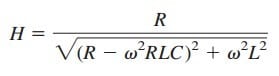
The corner frequency is the same as the half-power frequency, i.e., where H is reduced by a factor of 1√2. Since the dc value of H(ω) is 1, at the corner frequency, Equation.(1.3) becomes after squaring

or
 Substituting the values of R, L, and C, we obtain
![]()
Assuming that ωc is in krad/s,
 Solving the quadratic equation in ωc2, we get ωc2 = 0.5509, or
![]()
Passive Filters Example 2
If the bandstop filter in Figure.(8) is to reject a 200-Hz sinusoid while passing other frequencies, calculate the values of L and C. Take R = 150Ω and the bandwidth as 100 Hz.
Solution:
We use the formulas for a series resonant circuit in the previous post.
![]() But
But
![]()
Rejection of the 200-Hz sinusoid means that f0 is 200 Hz, so that ω0 in Figure.(9)
![]()
Since ω0 = 1/√(LC),