Radio Receiver Working Principle – Application of Resonance Circuit
After learning a lot about resonance circuit, we will learn about one of its application: the radio receiver.
Series and parallel resonant circuits are commonly used in radio and TV receivers to tune in stations and to separate the audio signal from the radio frequency carrier wave.
Radio Receiver
As an example, consider the block diagram of an AM radio receiver shown in Figure.(1).
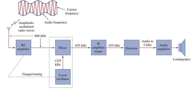
Incoming amplitude-modulated radio waves (thousands of them at different frequencies from different broadcasting stations) are received by the antenna.
A resonant circuit (or a bandpass filter) is needed to select just one of the incoming waves. The selected signal is very weak and is amplified in stages in order to generate an audible audio-frequency wave.
Thus we have the radio frequency (RF) amplifier to amplify the selected broadcast signal, the intermediate frequency (IF) amplifier to amplify an internally generated signal based on the RF signal, and the audio amplifier to amplify the audio signal just before it reaches the loudspeaker.
It is much easier to amplify the signal at three stages than to build an amplifier to provide the same amplification for the entire band.
The type of AM receiver shown in Figure.(1) is known as the superheterodyne receiver. In the early development of radio, each amplification stage had to be tuned to the frequency of the incoming signal.
This way, each stage must have several tuned circuits to cover the entire AM band (540 to 1600 kHz). To avoid the problem of having several resonant circuits, modern receivers use a frequency mixer or heterodyne circuit, which always produces the same IF signal (445 kHz) but retains the audio frequencies carried on the incoming signal.
To produce the constant IF frequency, the rotors of two separate variable capacitors are mechanically coupled with one another so that they can be rotated simultaneously with a single control; this is called ganged tuning.
A local oscillator ganged with the RF amplifier produces an RF signal that is combined with the incoming wave by the frequency mixer to produce an output signal that contains the sum and the difference frequencies of the two signals.
For example, if the resonant circuit is tuned to receive an 800-kHz incoming signal, the local oscillator must produce a 1255-kHz signal, so that the sum (1255+800=2055 kHz) and the difference(1255–800=455 kHz) of frequencies are available at the output of the mixer. However, only the difference, 455 kHz, is used in practice. This is the only frequency to which all the IF amplifier stages are tuned, regardless of the station dialed.
The original audio signal (containing the “intelligence”) is extracted in the detector stage. The detector basically removes the IF signal, leaving the audio signal. The audio signal is amplified to drive the loudspeaker, which acts as a transducer converting the electrical signal to sound.
Our major concern here is the tuning circuit for the AM radio receiver. The operation of the FM radio receiver is different from that of the AM receiver discussed here, and in a much different range of frequencies, but the tuning is similar.
Read also : sinusoidal waveform
Radio Receiver Example
The resonant or tuner circuit of an AM radio is portrayed in Figure.(2). Given that L = 1 µH, what must be the range of C to have the resonant frequency adjustable from one end of the AM band to another?

Solution:
The frequency range for AM broadcasting is 540 to 1600 kHz. We consider the low and high ends of the band. Since the resonant circuit in Figure.(2) is a parallel type.
From the equation in parallel resonance, we get

or

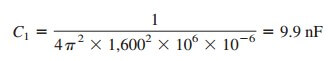
For the high end of the AM band, f0 = 1600 kHz, and the corresponding C is
For the low end of the AM band, f0 = 540 kHz, and the corresponding C is
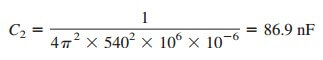 Thus, C must be an adjustable (gang) capacitor varying from 9.9 nF to 86.9 nF.