Active and Passive Elements in Electrical Circuits — The Real Backbone of Every System
If you’ve ever opened up an electrical panel or a circuit board, you know the feeling — dozens of components, wires, and connections staring back at you. Some of them seem to make things happen: they amplify, switch, or generate signals. Others just sit there quietly, doing their job without any drama.
That’s the difference between active and passive elements.
It might sound like textbook theory, but trust me — understanding how these two categories behave is what separates someone who can assemble circuits from someone who can design them. Once you see how energy flows between these elements, you’ll read schematics like a map and know exactly where a problem hides when things don’t work.
Let’s unpack this in a way that’s both real and relevant — from simple definitions to the equations and standards that guide actual engineering work.
What are Circuit Elements
A circuit element is an electrical device that affects voltage-current relationship in an electrical circuit.
They have their own voltage-current characteristic to make them able to change the voltage-current in the circuit as we desired.
When talking about circuit elements, most of you will mention electrical components such as resistor, capacitor, inductor, diode, etc. They are indeed the elements we need to build an electrical circuit.
Since there are a lot of electrical components, we can still categorize them into several circuit elements based on their characteristics.
Rather than mentioning the elements, it is easier to mention the types of circuit elements. Every element in the same type mostly shares the same characteristic with some difference in specifications and shapes.
We can list the types of electrical circuit elements below:
- Circuit element ports,
- Circuit element linearity, and
- Active and passive elements.
We will focus on active vs passive elements, but knowing the first two types briefly won’t cost us anything since they are also related to the active and passive elements.
Getting the Basics Right: What Are Active and Passive Elements?
When we talk about active and passive elements, we’re basically talking about how components handle energy.
- Active elements can supply or control energy. They can amplify current or voltage and usually need a little external push — a bias or a power source — to do their thing.
- Passive elements can’t amplify or generate power. They can store, dissipate, or transfer energy, but they always depend on an external source.
Here’s an easy way to picture it:
If your circuit were a team, active elements are the leaders — they take input and make things happen. Passive elements are the steady workers — they keep things balanced and reliable.
Formal Definition (IEC / IEEE Aligned)
According to IEEE and IEC conventions:
- Active elements are devices capable of controlling or amplifying electrical energy. They can introduce power into a circuit.
- Passive elements are components that consume or store electrical energy but cannot amplify or generate power.
That’s the official version. In practice, it’s about whether a component can provide power gain or not.
Why You Should Care
Here’s the real reason this matters.
When you’re troubleshooting or designing circuits, knowing which parts are active or passive helps you predict behavior. It’s the foundation of understanding:
- How signals are amplified or filtered.
- How to manage stability and biasing.
- How a system reacts under load or fault conditions.
Once you grasp this, you’ll stop memorizing circuit patterns and start thinking like current does — “Where can I go? What’s stopping me? Who’s controlling me?”
Active Elements in Electrical Circuits
Let’s start with the energy “drivers.”
Definition
An active element can control current or voltage, and it often needs an external power source to function. More importantly, it can provide power gain, which means the output power can be higher than the input signal power (not counting supply power, of course).
Common Active Components
Component | Function | Real-World Example |
Diode | Allows current in one direction | Power rectifier, voltage protection |
Transistor (BJT/FET) | Amplifies or switches current | Audio amplifier, digital logic circuit |
Operational Amplifier (Op-Amp) | Amplifies voltage difference | Filters, control loops, instrumentation |
SCR / Triac | Controls high power AC | Motor drives, lighting dimmers |
IC / Microcontroller | Combines active and passive behavior | Processors, control boards |
Most active devices today are semiconductor-based. Even something as simple as a diode is technically active because it controls current flow and has non-linear characteristics.
An active element is an electrical component which is capable of delivering energy to an electric circuit.
Characteristics of Active Elements
- Require biasing: They need an external source (DC supply or bias voltage).
- Can amplify signals: Output power > input power.
- Show non-linear I-V behavior: Especially true for transistors and most types of diode.
- Can control current or voltage: Often form the “brains” of the circuit.
If you’ve ever tuned an amplifier or designed a switching regulator, you’ve seen how critical these behaviors are.
Passive Elements in Electrical Circuits
Now, let’s talk about the quiet heroes — the passive elements.
Definition
A passive element cannot produce or amplify energy. It can only store it temporarily (like a capacitor or inductor) or dissipate it (like a resistor). But don’t underestimate them — without passive components, no active device would even operate correctly.
Passive elements are elements that are not capable of generating power. But, this element absorbs, stores, or dissipates energy flowing to it.
Common Passive Components
Component | Function | Typical Application |
Resistor | Limits or divides current | Voltage divider, current sensing |
Capacitor | Stores charge, filters signals | Power supply filter, timing circuit |
Inductor | Stores energy in magnetic field | Transformers, SMPS chokes |
Transformer | Transfers energy between circuits | Isolation, voltage conversion |
Passive elements are elements that are not capable of generating power. But, this element absorbs, stores, or dissipates energy flowing to it.
Characteristics of Passive Elements
- Don’t need an external source.
- Don’t amplify or generate signals.
- Usually linear (Ohm’s law applies).
- Defined by physical parameters — resistance (Ω), capacitance (F), inductance (H).
If you ever replaced a burnt resistor or a swollen capacitor, you already know: passive parts quietly handle the stress that active parts create.
Active vs Passive Elements: A Quick Comparison
Here’s a side-by-side summary you can keep in mind:
Property | Active Elements | Passive Elements |
Power Source | Need external supply | Don’t need external supply |
Power Gain | Can amplify | No amplification |
Linearity | Often non-linear | Usually linear |
Function | Control or amplify signals | Store or dissipate energy |
Examples | Transistor, diode, IC | Resistor, capacitor, inductor |
You can think of it like this — active elements decide what happens in a circuit, while passive ones shape how it happens.
Equations and Core Principles
To understand how each behaves, you have to look at their governing relationships.
Resistor (Passive)
Ohm’s Law:
\( V = I \times R \)
where:
\( V \) : voltage in volt
\( I \) : current in ampere
\( R \) : resistance in ohm (Ω)
Power dissipated:
\( P = I^2 R = \frac{V^2}{R} \)
It’s simple, but this single relationship defines most passive behavior.
Capacitor (Passive)
\( I = C \frac{dV}{dt} \)
\( C \) : capacitance (farad)
\( \frac{dV}{dt} \) : rate of voltage change
Energy stored:
\( E = \frac{1}{2} C V^2 \)
A capacitor stores energy as an electric field. When voltage changes, it releases that energy to stabilize the circuit — that’s why power supplies use big filter caps.
Inductor (Passive)
\( V = L \frac{dI}{dt} \)
\( L \) : inductance (henry)
\( \frac{dI}{dt} \) : rate of current change
Stored energy:
\( E = \frac{1}{2} L I^2 \)
An inductor resists change in current — perfect for smoothing current in switching circuits.
Transistor (Active)
For a BJT (Bipolar Junction Transistor):
\( I_C = \beta I_B \)
Where \( \beta \) (beta) is the current gain. This is the essence of amplification — a small base current controls a much larger collector current.
Circuit Element Linearity
This type will divide circuit elements into linear and nonlinear elements. Keep in mind, what we use in the circuit will affect what circuit analysis we should use.
Linear elements
This type of element follows the linearity between voltage and current even if the phase is shifted. The examples of this type are resistor, inductor, capacitor, and dependent source. The main idea is that the output waveform is the same with the input waveform regardless of the magnitude and the phase.
These elements will not cause distortion and can be analyzed easily. The examples of linear components are resistor, capacitor, and inductor.
Below is an example of linearity of a resistor.

Below is an example of linearity of an inductor.

Below is an example of linearity of a capacitor

Keep in mind that both inductor and capacitor are suitable for AC circuits rather than DC circuits.
Nonlinear elements
This type of element will follow the nonlinear relationship between voltage and current. This element will cause distortion and the example of it is a diode.
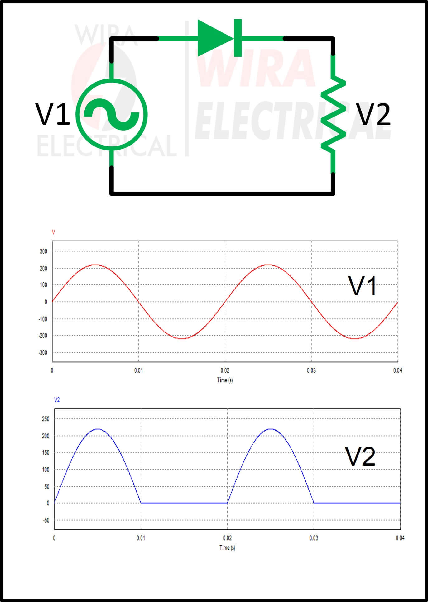
You will find it harder to analyze this type of element. But it doesn’t matter, we don’t need to understand it right now.
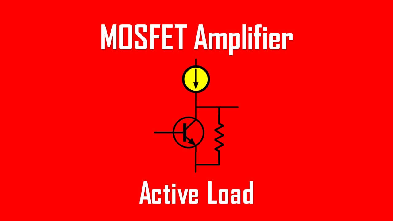
Real Circuit Example
Let’s walk through a simple amplifier circuit.
- Resistors: Set the biasing levels — passive.
- Capacitors: Block DC, couple AC — passive.
- Transistor: Amplifies the signal — active.
- Power supply: Provides the energy — active source.
Everything works together. Remove the passive parts, and your transistor saturates or oscillates. Remove the active parts, and your circuit just sits there doing nothing. It’s a symbiotic system.
Applications You See Every Day
1. Power Supplies
- Active: Diodes and regulators convert and stabilize DC output.
- Passive: Capacitors and inductors smooth the ripples.
2. Amplifiers
- Active: Transistors and op-amps handle the gain.
- Passive: RC networks set bandwidth and frequency response.
3. Communication Systems
- Active: Oscillators and mixers create and process signals.
- Passive: Filters and antennas handle transmission and reception.
4. Motor Control
- Active: SCRs and IGBTs manage power flow.
- Passive: Snubber networks and filters protect against spikes.
Once you start seeing circuits this way, it’s easier to figure out what each part contributes.
Advantages and Disadvantages
Type | Advantages | Limitations |
Active | Amplify, control, and switch signals; enable logic and automation | Need power, can overheat, sensitive to noise |
Passive | Simple, reliable, no external supply, linear behavior | No amplification, limited control, can cause losses |
Good designs balance both. You’ll rarely find an all-active or all-passive circuit doing something useful.
Testing and Identifying Components
When you pick up a part and wonder if it’s active or passive, here’s a quick mental checklist:
- Does it need power? If yes — probably active.
- Can it amplify or control current? If yes — definitely active.
- Does it just store or drop voltage? That’s passive.
- Use a multimeter:
- If polarity matters (like a diode or transistor), it’s active.
- If it behaves the same both ways (like a resistor), it’s passive.
It’s simple logic that works even in complex assemblies.
Why Active and Passive Elements Are So Important
Here’s the big picture:
You can’t design stable, efficient circuits without understanding how active and passive components share energy.
- Passives define impedance, time constants, and stability.
- Actives define control, amplification, and functionality.
Even in highly integrated ICs, the same rule applies. Inside every chip, there’s a network of microscopic resistors, capacitors, and transistors — all obeying the same principles.
So, whether you’re debugging a motor drive or designing a microcontroller circuit, you’re still working with the same foundation.
Tips, Best Practices, and Common Pitfalls
Best Practices
- Always bias active devices correctly — refer to datasheets and IEC guidelines.
- Use passive elements to stabilize gain or filter unwanted frequencies.
- Respect voltage and power ratings (IEC 60115 for resistors, IEC 60384 for capacitors).
- Plan for heat dissipation, especially with active devices.
Common Mistakes
- Using a transistor without proper bias — it either saturates or does nothing.
- Ignoring ESR in capacitors, which can cause instability.
- Assuming all inductors behave ideally — core losses matter.
- Forgetting that transformers, although passive, can change impedance dramatically.
If you’ve ever built a circuit that oscillated when it shouldn’t — chances are you mixed up how these elements interact.
Quick Recap
Let’s tie it all together:
- Active elements can amplify, switch, or generate energy.
- Passive elements can store or dissipate energy.
- Both are essential — one gives control, the other gives structure.
- Knowing the difference improves design accuracy, efficiency, and safety.
If you’ve followed through this far, you’re already thinking like someone who understands circuits, not just reads them.
FAQ — Real Questions Engineers Ask
Q1: What are active and passive elements in simple terms?
Active components supply or amplify energy. Passive ones just consume or store it.
Q2: How can I tell if a component is active or passive?
Check if it needs an external source or can amplify — if yes, it’s active.
Q3: Are LEDs considered active?
Yes. They require external current and convert electrical energy into light.
Q4: What about diodes? Aren’t they passive?
Diodes are technically active because they control current flow in a non-linear way.
Q5: Can I build a circuit with only passive components?
Sure — RC filters, voltage dividers, and attenuators work fine. But you’ll never get amplification.
Q6: Why does this classification matter?
Because it affects biasing, power supply design, safety, and how a circuit behaves dynamically.
References and Further Reading
- IEC 60115 – Fixed Resistors for Use in Electronic Equipment
- IEC 60384 – Fixed Capacitors for Electronic Equipment
- IEC 61010 – Safety Requirements for Electrical Equipment
- IEEE 315-1975 – Graphic Symbols for Electrical and Electronics Diagrams
- Sedra & Smith, Microelectronic Circuits, Oxford University Press
- Alexander & Sadiku, Fundamentals of Electric Circuits, McGraw-Hill
- Horowitz & Hill, The Art of Electronics, Cambridge University Press
Final Thoughts
Every circuit tells a story of balance — control versus stability, amplification versus dissipation. Active and passive elements are the characters that make that story happen.
The more you understand their roles, the more intuitive circuit design becomes. So next time you’re debugging a board or sketching a schematic, take a second to ask yourself — who’s driving the action, and who’s keeping it steady?
Once you can answer that, you’re already engineering like a pro.