Difference Amplifier Equation Example and Simple Circuit Design
Difference amplifier is used to amplify the difference between the inputs. Along with the circuit design, we will also learn the difference amplifier equation here.
After learning what is operational amplifier, we will also learn:
- Ideal op amp
- Summing amplifier
- Difference amplifier
- Cascaded op amp circuits
- Digital to analog converter
Difference Amplifier Equation
Difference (or differential) amplifiers are used in various applications where there is a need to amplify the difference between two input signals. They are first cousins of the instrumentation amplifier, the most useful and popular amplifier.
A difference amplifier is a device that amplifies the difference between two inputs but rejects any signals common to the two inputs.
Consider the op amp circuit shown in Figure.(1).

Keep in mind that zero currents enter the op amp terminals. Applying KCL to node a,

Applying KCL to node b,

But va = vb. Substituting Equation.(2) into Equation.(1) yields
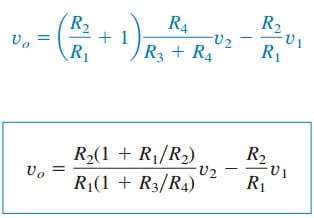
Since a difference amplifier must reject a signal common to the two inputs, the amplifier must have the property that
vo = 0 when v1 = v2.
This property exists when

Thus, when the op amp circuit is a difference amplifier, Equation.(3) becomes

If R2 = R1 and R3 = R4, the difference amplifier becomes a subtractor, with the output

Read also : what is ohm law
Difference Amplifier Examples
1. Design an op amp circuit with inputs v1 and v2 such that
vo = −5v1 + 3v2.
Solution:
The circuit requires that

This circuit can be realized in two ways.
Design 1 – If we desire to use only one op amp, we can use the op amp circuit of Figure.(1). Comparing Equation. (1.1) with Equation.(3), we see

Also,

If we choose R1 = 10 k Ω and R3 = 20 k Ω, then R2 = 50 k Ω and R4 = 20 kΩ.
Design 2 – If we desire to use more than one op amp, we may cascade an inverting amplifier and a two-input inverting summer, as shown in Figure.(2).
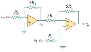
For the summer,

and for the inverter,

Combining Equations.(1.4) and (1.5) gives
![]()
which is the desired result. In Figure.(2), we may select R1 = 10 kΩ and R3 = 20 kΩ or R1 = R3 = 10 kΩ.
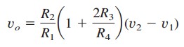
2. An instrumentation amplifier shown in Figure.(3) is an amplifier of low-level signals used in process control or measurement applications and commercially available in single-package units.

Show that
Solution:
We recognize that the amplifier A3 in Figure.(3) is a difference amplifier. Thus, from Equation.(5),

Since the op amps A1 and A2 draw no current, current i flows through the three resistors as though they were in series. Hence,

But

and va = v1, vb = v2. Therefore,

Inserting Equations.(2.2) and (2.3) into (2.1) gives

as required.