We know that dc is produced by batteries. But how we produce ac? One of the simple solutions is the wien bridge oscillator circuit.
Make sure to read what is ac circuit first.
Make sure to read:
- What is phasor
- Impedance and admittance
- Kirchhoff’s laws for ac circuit
- Power calculation in ac circuit
- Three phase circuit
And its applications:
One way is using oscillators, which are circuits that convert dc to ac.
An oscillator is a circuit that produces an ac waveform as output when powered by a dc input.
Wien Bridge Oscillator
The only external source an oscillator needs is the dc power supply. Ironically, the dc power supply is usually obtained by converting the ac supplied by electric utility company to dc.
Having gone through the trouble of conversion, you may wonder why we need to use the oscillator to convert the dc to ac again.
The problem is that the ac supplied by the utility company operates at a preset frequency of 60 Hz in some country such as United States and 50 Hz in some other nations.
Whereas many applications such as electronic circuits, communication systems, and microwave devices require internally generated frequencies that range from 0 to 10 GHZ or higher.
Oscillators are used for generating these frequencies.
In order for sine wave oscillators to sustain oscillations, they must meet the Barkhausen criteria :
- The overall gain of the oscillator must be unity or greater. Therefore, losses must be compensated for by an amplifying device.
- The overall phase shift (from input to output and back to the input) must be zero.
Three common types of sine wave oscillators are phase-shift, twin T, and Wien-bridge oscillators.
Here we consider only the Wien-bridge oscillator.
The Wien-bridge oscillator is widely used for generating sinusoids in the frequency range below 1 MHz.
It is an RC op amp circuit with only a few components, easily tunable and easy to design.
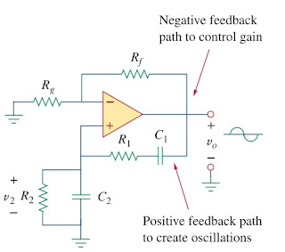
As shown in Figure.(1), the oscillator essentially consists of a noninverting amplifier with two feedback paths : The positive feedback path to the noninverting input creates oscillations, while the negative feedback path to the inverting input controls the gain.
 |
| Figure 1. Wien Bridge Oscillator |
If we define the impedances of the RC series and parallel combinations as Zs and Zp, then
 |
| (1) |
 |
| (2) |
The feedback ratio is
 |
| (3) |
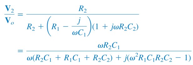
Substituting Equations.(1) and (2) to (3) gives
 |
| (4) |
To satisfy the second Barkhausen criterion, V2 must be in phase with Vo, which implies that the ratio in Equation.(4) must be purely real.
Thus, the imaginary part must be zero. Setting the imaginary part equal to zero gives the oscillation frequency ωo as
or
 |
| (5) |
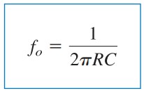
In most practical applications, R1 = R2 = R and C1 = C2 = C, so that
 |
| (6) |
or
 |
| (7) |
Substituting Equations.(6) and R1 = R2 = R, C1 = C2 = C into Equation.(4) results
 |
| (8) |
Hence, in order to satisfy the first Barkhausen criterion, the op amp must compensate by providing the gain of 3 or greater so that the overall gain is at least 1 or unity.
We recall that for a noninverting amplifier,
 |
| (9) |
or
 |
| (10) |
Due to the inherent delay caused by the op amp, Wien-bridge oscillators are limited to operating in the frequency range of 1 MHz or less.
Read also : laplace transform convolution
Wien Bridge Oscillator Circuit
For better understanding let us review the example below :
Design a Wien-bridge oscillators circuit at 100 kHz
Solution :
Using Equation.(7), we get the time constant of the circuit as
 |
| (1.1) |
If we select R = 10 kΩ, then we can select C = 159 pF to satisfy Equation.(1.1). Since the gain must be 3, Rf/Rg = 2. We could select Rf = 20 kΩ while Rg = 10 kΩ.
