Cascaded Op Amp Circuits
Cascaded op amp circuits mean we use multiple op amp connected together head to tail. These op amps form multistage, which amplify each op amp’s output each stage.
After learning what is operational amplifier, we will also learn:
- Ideal op amp
- Summing amplifier
- Difference amplifier
- Cascaded op amp circuits
- Digital to analog converter
Cascaded Op Amp Circuits
As we know, op amp circuits are modules or building blocks for designing complex circuits. It is often necessary in practical applications to connect op amp circuits in cascade (i.e., head to tail) to achieve a large overall gain. In general, two circuits are cascaded when they are connected in tandem, one behind another in a single file.
A cascade connection is a head-to-tail arrangement of two or more op amp circuits such that the output of one is the input of the next.
When op amp circuits are cascaded, each circuit in the string is called a stage; the original input signal is increased by the gain of the individual stage. Op amp circuits have the advantage that they can be cascaded without changing their input -output relationships.
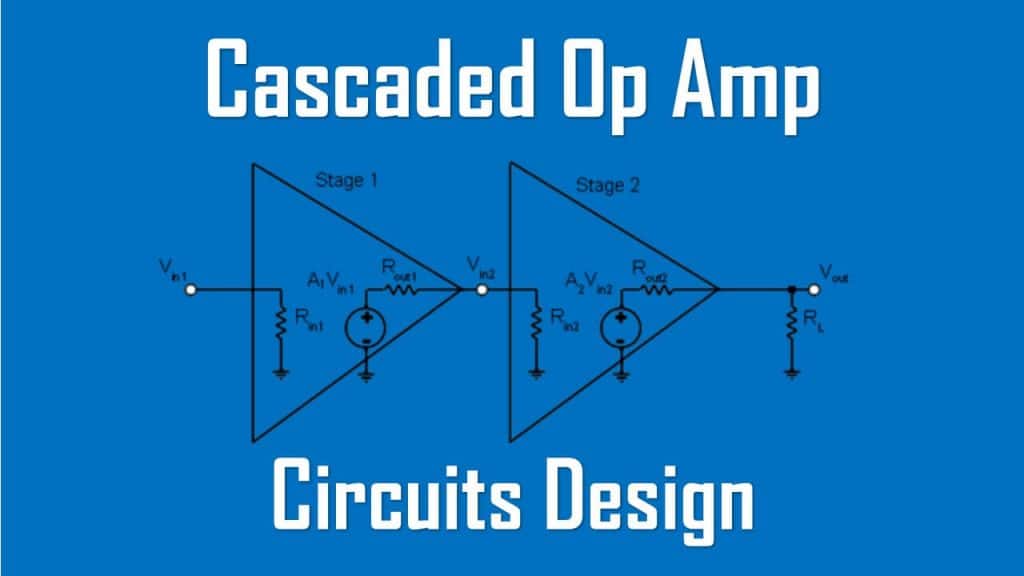
This is due to the fact that each (ideal) op amp circuit has infinite input resistance and zero output resistance. Figure.(1) displays a block diagram representation of three op amp circuits in cascade.

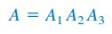
Since the output of one stage is the input to the next stage, the overall gain of the cascade connection is the product of the gains of the individual op amp circuits, or
Although the cascade connection does not affect the op amp input-output relationships, care must be exercised in the design of an actual op amp circuit to ensure that the load due to the next stage in the cascade does not saturate the op amp.
Read also : Thevenin and Norton AC circuits
Cascaded Op Amp Circuits Examples
1. Find vo and io in the circuit in Figure.(2).

Solution:
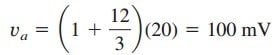
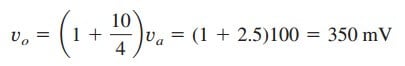
This circuit consists of two non-inverting amplifiers cascaded. At the output of the first op amp,
 At the output of the second op amp,
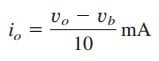
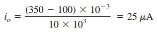
The required current io is the current through the 10-kΩ resistor.
But vb = va = 100 mV. Hence,
2. If v1 = 1 V and v2 = 2 V, find vo in the op amp circuit of Figure.(3)

Solution:
1. Define. The problem is clearly defined.
2. Present. With an input of v1 of 1 V and of v2 of 2 V, determine the output voltage of the circuit shown in Figure 5.31. The op amp circuit is actually composed of three circuits. The first circuit acts as an amplifier of gain −3(−6 kΩ∕2 kΩ) for v1 and the second functions as an amplifier of gain −2(−8 kΩ∕4 kΩ) for v2.
The last circuit serves as a summer of two different gains for the output of the other two circuits.
3. Alternative. There are different ways of working with this circuit. Because it involves ideal op amps, then a purely mathematical approach will work quite easily. A second approach would be to use PSpice as a confirmation of the math.
4. Attempt. Let the output of the first op amp circuit be designated as v11 and the output of the second op amp circuit be designated as v22. Then we get
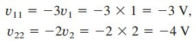 In the third circuit, we have
5. Evaluate. To properly evaluate our solution, we need to identify a reasonable check. Here we can easily use PSpice to provide that check.
Now we can simulate this in PSpice. The results are shown in Figure.(4).

We obtain the same results using two entirely different techniques (the fist is to treat the op amp circuits as just gains and summer and the second is to use circuit analysis with PSpice). This is a very good method of assuring that we have the correct answer.
6. Satisfactory? We are satisfied we have obtained the asked for results. We can now present our work as a solution to the problem.