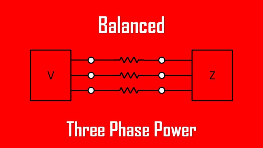
Balanced Three Phase Power
Balanced three phase power can only be achieved if our three phase circuit has both balanced three phase voltage and balanced three phase load.
We need to make sure our voltage and current in our electrical circuit have the same sinusoidal waveform even with shifted phase angle. Its power factor should be consistent across all three phases.
Balanced Three Phase Power Formula
When dealing with an AC circuit we need to use time-domain and frequency-domain calculations.
Assume we have a balanced three phase system with balanced wye-connected load, the phase voltages are
where the factor √2 is necessary because Vp has been defined as the rms value of the phase voltage.
If ZY = Z∠θ, the phase currents lag behind their corresponding phase voltages by θ. Thus,
where Ip is the rms value of the phase current.
The total instantaneous power in the load is the sum of the instantaneous powers in the three phases; that is,
Applying the trigonometric identity
![]()
gives
Thus the total instantaneous power in a balanced three-phase system is constant—it does not change with time as the instantaneous power of each phase does.
This result is true whether the load is wye- or delta-connected.
This is one important reason for using a three-phase system to generate and distribute power. We will look into another reason a little later.
Since the total instantaneous power is independent of time, the average power per phase Pp for either the delta-connected load or the wye-connected load is p/3, or
![]()
and the reactive power per phase is
![]()
The apparent power per phase is
![]()
The complex power per phase is
![]()
where Vp and Ip are the phase voltage and phase current with magnitudes Vp and Ip, respectively.
If you are not familiar with complex power, a complex power is the vector value which represents both active (real) and reactive power. The apparent power is the absolute magnitude of the complex power.
Complex power represents how much power is doing work (real) and power that is oscillating back and forth in a circuit (reactive). Apparent power is the total power supplied to the circuit regardless if it is used for work or oscillating.
The total average power is the sum of the average powers in the phases:

For a wye-connected load, IL = Ip but VL = √3Vp, whereas for a delta-connected load, IL = √3Ip but VL = Vp.
Thus, this equation applies for both wye-connected and delta-connected loads. Similarly, the total reactive power is
![]()
and the total complex power is

where Zp = Zp∠θ is the load impedance per phase. (Zp could be ZY or Z∆)
Alternatively, we may rewrite the equation as
![]()
Remember that Vp, Ip, VL, and IL are all rms values and that θ is the angle of the load impedance or the angle between the phase voltage and the phase current.
A second major advantage of three-phase systems for power distribution is that the three-phase system uses a lesser amount of wire than the single-phase system for the same line voltage VL and the same absorbed power PL.
We will compare these cases and assume in both that the wires are of the same material (e.g., copper with resistivity ρ), of the same length l, and that the loads are resistive (i.e., unity power factor).
Let us observe a single phase system below with two wires.
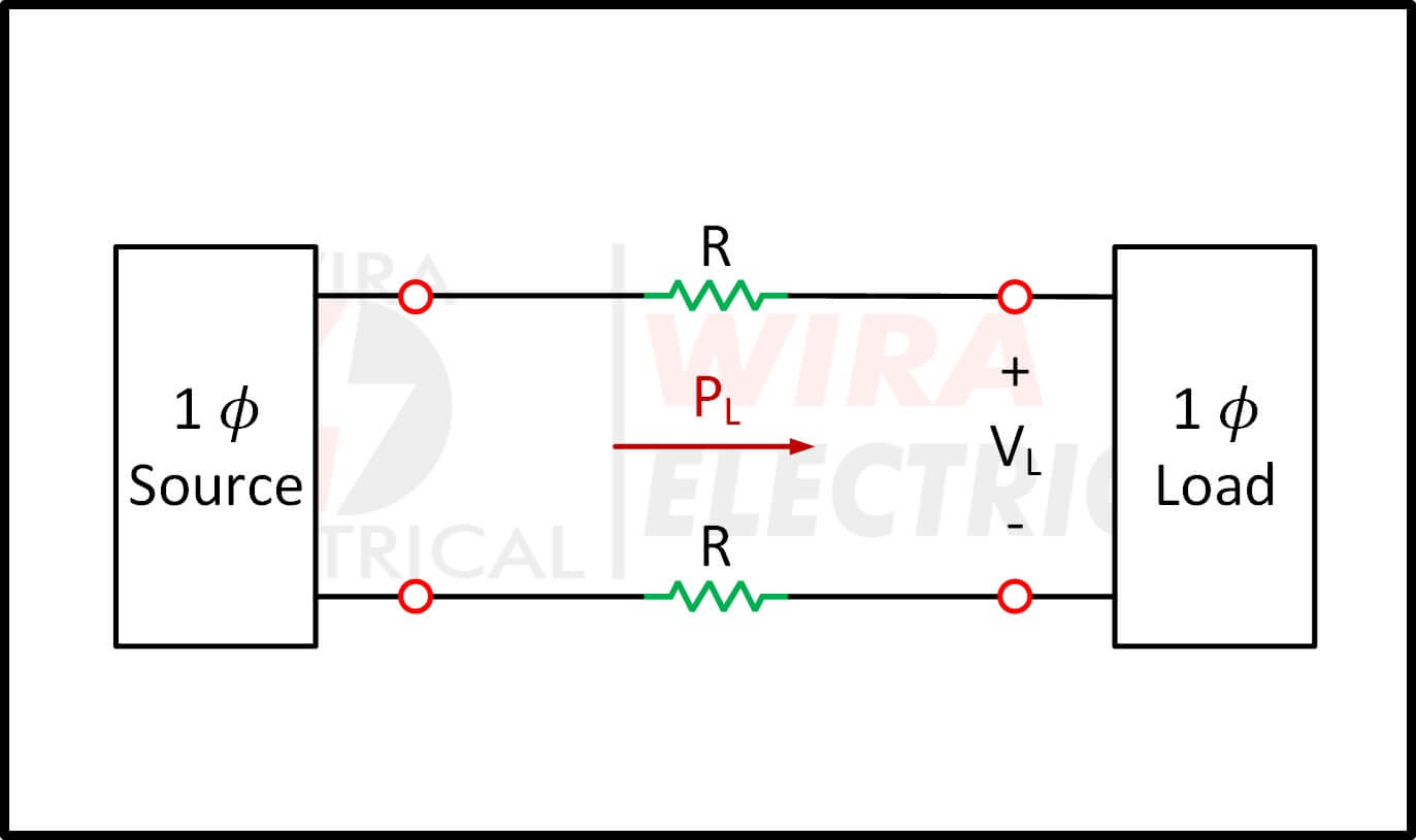
For the two-wire single-phase system above, IL = PL/VL, so the power loss in the two wires is

For the three-wire three-phase system three wires, I’L = |Ia| = |Ib| = |Ic| = PL/√3VL from the previous equation.

The power loss in the three wires is

Equations above show that for the same total power delivered PL and same line voltage VL,
R = ρl/πr2 and R’ = ρl/πr2, where r and r’ are the radii of the wires. Thus,
If the same power loss is tolerated in both systems, then r2 = 2r’2. The ratio of material required is determined by the number of wires and their volumes, so
since r2 = 2r’2.
Equation above shows that the single-phase system uses 33 percent more material than the three-phase system or that the three-phase system uses only 75 percent of the material used in the equivalent single-phase system.
In other words, considerably less material is needed to deliver the same power with a three-phase system than is required for a single-phase system.
Power in Balanced Three Phase System
It is no fun if we know a circuit has a balanced three phase power from the beginning. Now we will learn why a three phase power can only be generated if the source and load are balanced across all phases.
1. Refer to the circuit below. Determine the total average power, reactive power, and complex power at the source and at the load. We can see the voltage sources have equal magnitude across all phases only with shifted phase angle, the same applies to our loads.

It is sufficient to consider one phase, as the system is balanced. For phase a,
The real or average power supplied is −2087 W and the reactive power is −834.6 VAR.
At the load, the complex power absorbed is
![]()
where Zp = 10 + j8 = 12.81∠38.66o and Ip = Ia = 6.81∠−21.8o.
Hence
The real power absorbed is 1391.7 W and the reactive power absorbed is 1113.3 VAR.
The difference between the two complex powers is absorbed by the line impedance (5 − j2) Ω.
To show that this is the case, we find the complex power absorbed by the line as
which is the difference between Ss and SL, that is, Ss + Sl + SL = 0, as expected.
2. A three-phase motor can be regarded as a balanced wye-load. A three-phase motor draws 5.6 kW when the line voltage is 220 V and the line current is 18.2 A. Determine the power factor of the motor.
Answer:
The apparent power is
![]()
Since the real power is
![]()
the power factor is
3. Two balanced loads are connected to a 240-kV rms 60-Hz line, as shown below.

Load 1 draws 30 kW at a power factor of 0.6 lagging, while load 2 draws 45 kVAR at a power factor of 0.8 lagging.
Assuming the abc sequence, determine:
(a) the complex, real, and reactive powers absorbed by the combined load,
(b) the line currents, and
(c) the kVAR rating of the three capacitors delta-connected in parallel with the load that will raise the power factor to 0.9 lagging and the capacitance of each capacitor.
Answer:
(a) For load 1, given that P1 = 30 kW and cos θ1 = 0.6, then sin θ1 = 0.8.
Hence,
![]()
and Q1 = S1 sin θ1 = 50(0.8) = 40 kVAR. Thus, the complex power due to load 1 is
![]()
For load 2, if Q2 = 45 kVAR and cos θ2 = 0.8, then sin θ2 = 0.6. We find
![]()
and P2 = S2 cos θ2 = 75(0.8) = 60 kW. Therefore the complex power due to load 2 is
![]()
The total complex power absorbed by the load is
![]()
which has a power factor of cos 43.36o = 0.727 lagging. The real power is then 90 kW, while the reactive power is 85 kVAR.
(b) Since S = √3VLIL, the line current is
We apply this to each load, keeping in mind that for both loads, VL = 240 kV. For load 1,
Since the power factor is lagging, the line current lags the line voltage by θ1 = cos−1 0.6 = 53.13o. Thus,
![]()
For load 2,
and the line current lags the line voltage by θ2 = cos−1 0.8 = 36.87o.
Hence,
![]()
The total line current is
Alternatively, we could obtain the current from the total complex power using
and
![]()
which is the same as before. The other line currents, Ib2 and Ica, can be obtained according to the abc sequence (i.e., Ib = 297.82∠−163.36o mA and Ic = 297.82∠76.64o mA).
(c) We can find the reactive power needed to bring the power factor to 0.9 lagging,
![]()
where P = 90 kW, θold = 43.36o, and θnew = cos−1 0.9 = 25.84o.
Hence,
![]()
This reactive power is for the three capacitors. For each capacitor, the rating Q’C = 13.8 kVAR. The required capacitance is
Since the capacitors are delta-connected as shown below, Vrms in the above formula is the line-to-line or line voltage, which is 240 kV.

Thus,