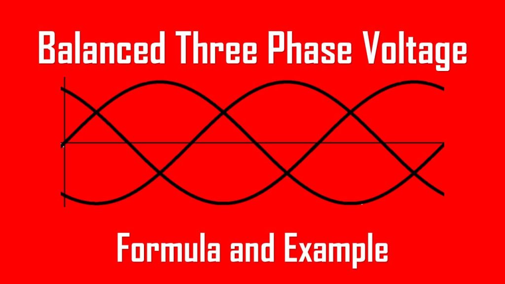
Balanced Three Phase Voltage
Three phase voltage is often generated by a three phase AC generator (or alternator) with a configuration shown below. It has a rotating part made from a magnet as a rotor, and stationary winding as the stator.

The waveforms generated by this generator will likely be

In our modern industrial time, bigger machines are not uncommon to be used massively. Three phase motors are widely used for their power transfer efficiency and simplicity compared to three single phase motors combined together.
But since we integrate three single phase motors into one three phase motor, our motor drive, electrical circuit, and stability need to be improved. For stability, we need a stable three phase voltage and current to produce balanced three phase power. This time we will learn about balanced three phase voltage.
Balanced Three Phase System
Balanced three phase system is a must for our equipment to deliver efficient energy and have a long lifetime. The unbalanced three phase system (along with harmonic disturbance) will likely reduce its efficiency and lifetime.
Just like what we have learnt about power factor correction, many countries charge us with apparent power (VA) instead of active power (W) since our equipment also generates reactive power that increases our wasted energy. This reactive power is not consumable or available energy to use, only a waste and disturb our equipment’s reliability.
In a balanced three phase system, the three phase supply is equal to each other, and the current drawn by each phase is equal. This indicates that not only the supply is balanced, the load is also balanced.
We will now learn about the easiest first, the balanced three phase loads.
We will use full inductive loads since our focus here is a three phase voltage supplying a three phase motor. Electrical motors are built with windings that represent an inductor.
Below is a balanced three phase load.

In a balanced three phase system, both the total electrical voltage and current in the electrical circuit are simply the sum of electrical voltage and current each phase. This fulfills the Kirchhoff’s Voltage Law and Kirchhoff’s Current Law.
The sum of the electrical current entering and leaving at any node is zero.
The sum of the electrical voltage in a closed loop is zero.
Both neutral electrical voltage and current are zero in a balanced three phase circuit.
Balanced Three Phase Voltage
Balanced three phase voltage is a three phase AC circuit that has three single phase sinusoidal waveforms which have equal magnitudes and frequency but shifted by 120° from each other. With phase A as a reference, it can lead or lag the other voltage (B and C).
Just as the three phase generator shown on the top, the windings are separated at 120° from each other. This way, generating three phase voltage is plausible.

The pair of a-a’, b-b’, and c-c’ are mechanically placed apart from each other by 120° around the stator.
As the rotor rotates, its magnetic field “cuts” the flux from the three coils and induces voltages in the coils.
Because the coils are placed 120° apart, the induced voltage in the coils are equal in magnitude but out of phase by 120°.
A three phase circuit always has each phase voltage shifted 120° from each other. Assume that the loads are already balanced, the electrical current in each phase is also balanced.
Below is the balanced three phase voltage where their magnitudes and frequency are equal, shifted 120° from each other.

To prove the Kirchhoff’s Voltage Law is fulfilled in a balanced three phase voltage, observe the graph below.

We can say that at any point, the sum of the three phase voltage is always zero. For example, Va is equal to the sum of Vb and Vc.
A three-phase system is equivalent to three single-phase circuits. The voltage sources can be either wye-connected (left) or delta connected (right) as shown below

Let us analyze briefly the wye-connected voltage source first. The voltages in the circuit are Van, Vbn, and Vcn are respectively between lines a, b, and c, and the neutral line n.
These phase voltages have equal amplitude and frequency with 120° phase shift from each other. Assume that voltages are balanced, hence
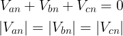
It concludes that
Balanced phase voltages are equal in magnitude and are out of phase with each other by 120°.
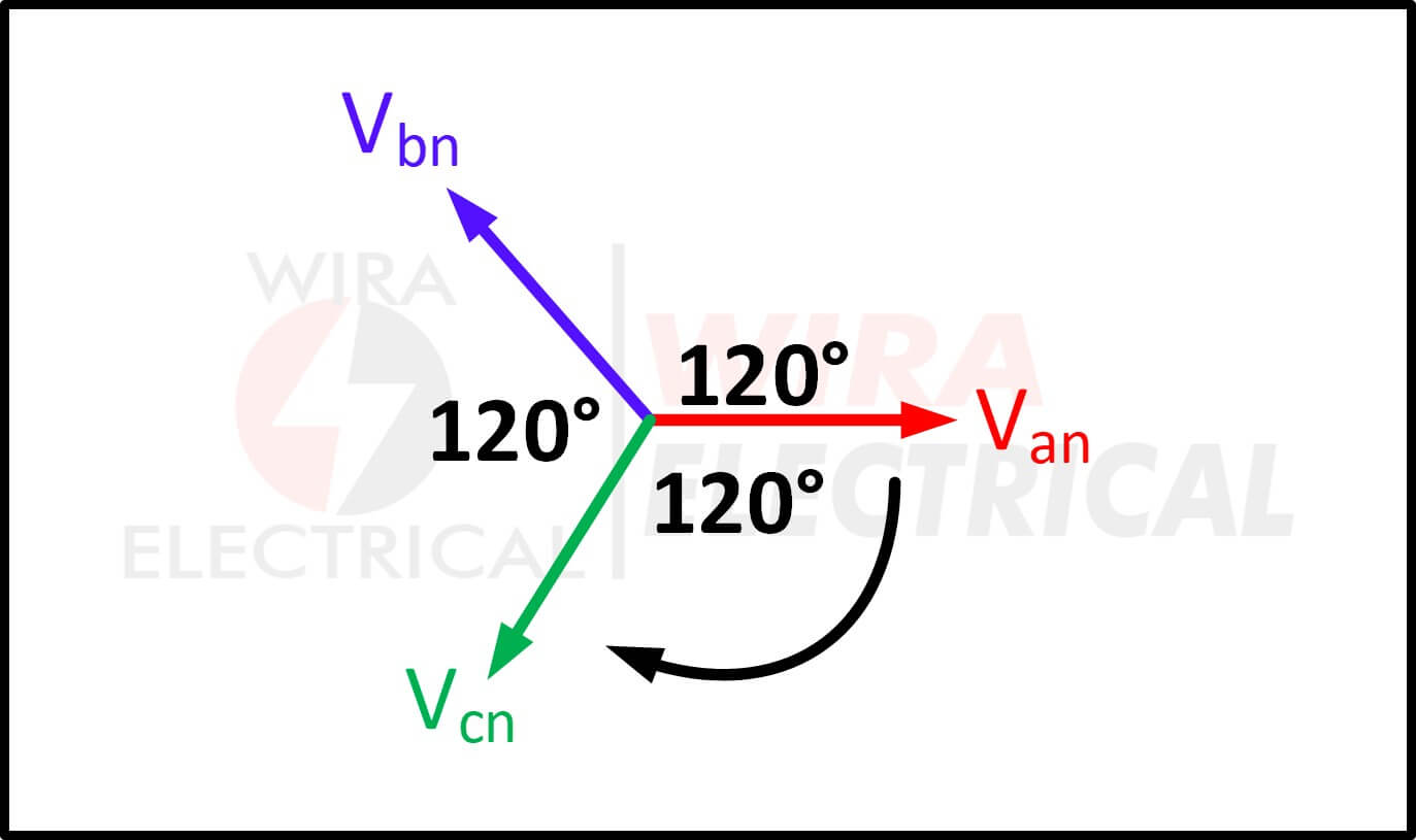
How to define 3 phase balanced supply with phasor diagram?
Since we have a three phase voltage shifted by 120° apart from each other, we can’t tell its sequence. It can be Van, Vbn, Vcn, or Van, Vcn, Vbn. Those two sequences are still correct as shown below.
We will use the abc sequence or positive sequence, where the sequence is Van leads Vbn, then Vbn leads Vcn

Van → Vbn → Vcn
This sequence is produced when the rotor in the illustration above rotates counterclockwise. The mathematical expressions are:
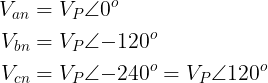
Where Vp is the effective or rms voltage.
If the rotor rotates in clockwise direction, we will get acb sequence or negative sequence. We will get the Van leads Vcn, then Vcn leads Vbn.
Van → Vcn → Vbn
The mathematical expressions are:

To prove the Kirchhoff’s Voltage Law is valid
We conclude that:
The phase sequence is the time order in which the voltages pass through their respective maximum values.
Keep in mind that in order we get balanced three phase power, we need to get the balanced three phase current. The three phase current can be obtained if our three phase circuit has both balanced three phase voltage and balanced three phase load.
Since both the three phase source and the three phase load can be either wye or delta connected, we have four possible connection :
- Balanced wye-wye connection
- Balanced wye-delta connection
- Balanced delta-delta connection
- Balanced delta-wye connection
Balanced Three Phase Voltage Example
Determine the phase sequence of the set of voltages
Answer :
The voltages can be expressed in phasor form as
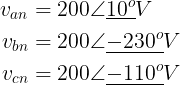
We notice that Van leads Vcn by 120° and Vcn, in turn, leads Vbn by 120°. Hence, we have an acb sequence.
Conclusion
A balanced three phase voltage is literally three single phase voltages with equal magnitude and frequency which are shifted by 120° from each other.
Equal magnitude means the peak and rms voltage from each phase has the same value at any point.
Equal frequency means they are oscillating with the same frequency. Their pulse widths are equal.
120° phase shift means their starting points are different by 120°, there are leads and lags between phases.
Balanced load means the load impedance of each phase connected to the three phase voltage sources are identical to each other.
Frequently Asked Questions
What is a balanced three-phase voltage?
Balanced three phase voltage is a three phase AC circuit that has three single phase sinusoidal waveforms which have equal magnitudes and frequency but shifted by 120° from each other. With phase A as a reference, it can lead or lag the other voltage (B and C).
What is balanced and unbalanced 3-phase?
Opposite to the balanced three phase, an unbalanced three phase is a three phase circuit where its voltage, current, or load has unequal amplitude or frequency with each other.
Why should 3 phases be balanced?
The balanced three phase system maintains the stable current and improves the power transfer from the supply to the load. Better power rating means less power waste and improves our equipment’s lifetime.
What causes 3 phase voltage imbalance?
The 3 phase voltage imbalance in a three phase AC circuit can be happening if the loads are not balanced to each other. This makes the voltage amplitude from each phase may have different amplitudes from each other.