Simple Thevenin and Norton Equivalent AC Circuits
Thevenin’s and Norton’s theorem are applied to ac circuits in the same way as they are to dc circuit.
- Node and supernode for ac circuit
- Mesh and supermesh for ac circuit
- Superposition for ac circuit
- Source transformation for ac circuit
- Thevenin and Norton for ac circuit
Thevenin’s and Norton’s Theorem for AC Circuit
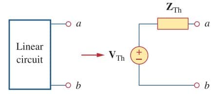
The frequency-domain version of a Thevenin equivalent circuit is drawn in Figure.(1), where a linear circuit is replaced by a voltage source in series with an impedance.
The Norton equivalent circuit is depicted in Figure.(2), where a linear circuit is replaced by a current source in parallel with an impedance.
 |
| Figure 1. Thevenin equivalent |
 |
| Figure 2. Norton equivalent |
Keep in mind that the two equivalent circuits are related as

just as in source transformation, VTh is the open-circuit voltage while IN is the short circuit current.
If the circuit has sources operating at different frequencies (will be shown in the example below), the Thevenin or Norton equivalent circuit has to be determined at each frequency.
This leads to entirely different equivalent circuits, one for each frequency, not one equivalent circuit with equivalent sources and equivalent impedances.
We will not cover the ‘step-by-step’ using these methods, make sure you learn it from the previous posts about Thevenin’s Theorem and Norton’s Theorem for dc circuit.
It is not that different from the ac circuit.
Read also : equivalent impedance AC circuits
Thevenin and Norton Equivalent AC Circuit Examples
For a better understanding let us review the examples below.
1. Obtain the Thevenin equivalent at terminals a-b of the circuit in Figure.(3).
 |
| Figure 3 |
Solution :
We find ZTh by setting the voltage source to zero. As shown in Figure.(4a), the 8 Ω resistance is now in parallel with -j6 reactance, so that their combination gives

Similarly, the 4 Ω resistance is in parallel with the j12 reactance, and their combination gives

 |
| Figure 4. Solution for Figure.(3) : (a) finding ZTh, (b) finding VTh |
The Thevenin impedance is the series combination of Z1 and Z2; that is,
To find VTh, consider the circuit in Figure.(4b). Currents I1 and I2 are obtained as

Applying KVL around the loop bcdeab in Figure.(4b) gives

or

2. Find the Thevenin equivalent of the circuit in Figure.(5) as seen from terminals a-b.
 |
| Figure 5 |
Solution :
Applying KVL to the loop on the right-hand side in Figure.(6a), we obtain
or

Hence, the Thevenin voltage is

 |
| Figure 6. The solution of Figure.(5) : (a) finding VTh, (b) finding ZTh |
To obtain ZTh, we remove the independent source.
Due to the presence of the dependent current source, we connect a 3 A current source (3 is an arbitrary value chosen for convenience here, a number divisible by the sum of currents leaving the node) to terminals a-b as shown in Figure.(6b). At the node, KCL gives

Applying KVL to the outer loop in Figure.(6b) gives

The Thevenin impedance is

3. Obtain current Io in Figure.(7) using Norton’s theorem.
 |
| Figure 7 |
Solution :
Our first objective is to find the Norton equivalent at terminals a-b. ZN is found in the same way as ZTh.
We set the sources to zero as shown in Figure.(8a). As evident from the figure, the (8 – j2) and (10 + j4) impedances are short-circuited, so that

To get IN, we short-circuit terminals a-b as in Figure.(8b) and apply mesh analysis.
Notice that meshes 2 and 3 form a supermesh because of the current source linking them. For mesh 1,
 |
| (3.1) |
 |
| Figure 8. Solution of the circuit in Figure.(7) : (a) finding ZN, (b) finding VN, (c) calculating Io |
For the supermesh,
| (3.2) |
At node a, due to the current source between meshes 2 and 3,
 |
| (3.3) |
Adding Equations.(3.1) and (3.2) gives
From Equation.(3.3),

The Norton current is

Figure.(8c) shows the Norton equivalent circuit along with the impedance at terminals a-b. By current division,