
Energy in a Coupled Electric Circuit
After learning what is the mutual inductance and dot convention, we will move on how to calculate the energy in a coupled electric circuit.
We can call an electric circuit as a coupled circuit if the circuit has a mutual inductance from two coils or inductors.
Energy in a Coupled Electric Circuit
We saw that the energy stored in an inductor is given by
 |
| (1) |
We now want to determine the energy stored in magnetically coupled coils.
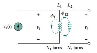
Consider the circuit in Figure.(1).
 |
| Figure 1. The circuit for deriving energy stored in a coupled circuit. |
We assume that currents i1 and i2 are zero initially so that the energy stored in the coils is zero.
If we let i1 increase from zero to I1while maintaining i2 = 0, the power in coil 1 is
 |
| (2) |
and the energy stored in the circuit is
 |
| (3) |
If we now maintain i1 = I1 and increase i2 from zero to I2, the mutual voltage induced in coil 1 is M12 di2/dt, while the mutual voltage induced in coil 2 is zero, since i1 does not change.
The power in the coils is now
| (4) |
and the energy stored in the circuit is
 |
| (5) |
The total energy stored in the coils when both i1 and i2 have reached constant values is
 |
| (6) |
If we reverse the order by which the currents reach their final values, that is, if we first increase i2 from zero to I2 and later increase i1 from zero to I1, the total energy stored in the coils is
 |
| (7) |
Since the total energy stored should be the same regardless of how we reach the final conditions, comparing Equations.(6) and (7) leads us to conclude that
 |
| (8a) |
and
 |
| (8b) |
This equation was derived based on the assumption that the coil currents both entered the dotted terminals.
If one current enters one dotted terminal while the other current leaves the other dotted terminal, the mutual voltage is negative so that the mutual energy MI1I2 is also negative.
In that case,
 |
| (9) |
Also, since I1 and I2 are arbitrary values, they may be replaced by i1 and i2, which gives the instantaneous energy stored in the circuit the general expression
 |
| (10) |
The positive sign is selected for the mutual term if both currents enter or leave the dotted terminals of the coils; the negative sign is selected otherwise.
We will now establish an upper limit for the mutual inductance M.
The energy stored in the circuit cannot be negative because the circuit is passive.
This means that the quantity 1/2L1i12 + 1/2L2i22 − Mi1i2 must be greater than or equal to zero,
 |
| (11) |
To complete the square, we both add and subtract the term i1i2√(L1L2) on the right-hand side of Equation.(11) and obtain
 |
| (12) |
The squared term is never negative; at its least, it is zero. Therefore, the second term on the right-hand side of Equation.(12) must be greater than zero; that is,
 |
| (13) |
Thus, the mutual inductance cannot be greater than the geometric mean of the self-inductances of the coils.
The extent to which the mutual inductance M approaches the upper limit is specified by the coefficient of coupling k, given by
 |
| (14) |
or
 |
| (15) |
where 0 ≤ k ≤ 1 or equivalently 0 ≤ M ≤ √(L1L2). The coupling coefficient is the fraction of the total flux emanating from one coil that links the other coil. For example, in Figure.(2),
 |
| (16) |
and in Figure.(3)
 |
| Figure 3. Mutual inductance M12 of coil 1 with respect to coil 2. |
 |
| (17) |
If the entire flux produced by one coil links another coil, then k = 1 and we have 100 percent coupling, or the coils are said to be perfectly coupled. Thus,
The coupling coefficient k is a measure of the magnetic coupling between two coils; 0 ≤ k ≤ 1.
For k < 0.5, coils are said to be loosely coupled; and for k > 0.5, they are said to be tightly coupled.
We expect k to depend on the closeness of the two coils, their core, their orientation, and their windings. Figure.(4) shows loosely coupled windings and tightly coupled windings.
 |
| Figure 4. Windings: (a) loosely coupled, (b) tightly coupled; cutaway view demonstrates both windings. |
The air-core transformers used in radio frequency circuits are loosely coupled, whereas iron-core transformers used in power systems are tightly coupled.
Read also : digital to analog converter formula
Energy in a Coupled Electric Circuit Example
Consider the circuit in Figure.(5). Determine the coupling coefficient. Calculate the energy stored in the coupled inductors at time t = 1 s if v = 60 cos (4 t + 30◦) V.
 |
| Figure 5 |
Solution:
The coupling coefficient is
indicating that the inductors are tightly coupled. To find the energy stored, we need to obtain the frequency-domain equivalent of the circuit.

The frequency-domain equivalent is shown in Figure.(6). We now apply mesh analysis. For mesh 1,
 |
| (1.1) |
For mesh 2

or
 |
| (1.2) |
Substituting this to Equation.(1.1) yields
and
In the time-domain,
At time t = 1 s, 4t = 4 rad = 229.2◦, and

The total energy stored in the coupled inductors is

 |
| Figure 6 |


Thanks for the solution
Firstly i think cos(4t+30) should be converted to a sin wave before cinverting to phasor form . But i am just thinking
Secondly conveting (-12-14j) to phasor, the quadrant should be considered . But I’m just thinking
Still correct though
Thank you! very well written.
THX THE SOLUTIONS ARE THE BEST. 1 IN A MILLION 😍😍