
What is Non-Inverting Op Amp Equation
Like inverting op amp, the non-inverting op amp equation is a must for us. The equation is not that different from the inverting one.
Non-Inverting Op Amp Equation
Another important application of the ideal op amp is the non-inverting amplifier shown in Figure.(1).
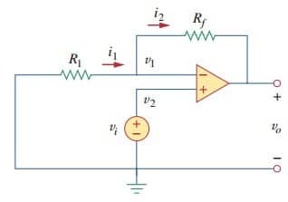
In this case, the input voltage vi is applied directly at the non-inverting input terminal, and resistor R1 is connected between the ground and the inverting terminal. We are interested in the output voltage and the voltage gain.
Application of KCL at the inverting terminal gives
But v1 = v2 = vi. Equation. (1) becomes

The voltage gain is Av = vo/vi = 1 + Rf/R1, which does not have a negative sign. Thus, the output has the same polarity as the input.
A non-inverting amplifier is an op amp circuit designed to provide a positive voltage gain.
Again we notice that the gain depends only on the external resistors.
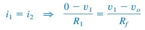
Notice that if feedback resistor Rf = 0 (short circuit) or R1 = ∞ (open circuit) or both, the gain becomes 1. Under these conditions (Rf = 0 and R1= ∞), the circuit in Figure.(1) becomes that shown in Figure.(2), which is called a voltage follower (or unity gain amplifier) because the output follows the input.
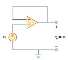
Thus, for a voltage follower
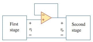
Such a circuit has a very high input impedance and is therefore useful as an intermediate-stage (or buffer) amplifier to isolate one circuit from another, as portrayed in Figure.(3). The voltage follower minimizes interaction between the two stages and eliminates interstage loading.
Read also : crossover network
Non-Inverting Op Amp Equation Example
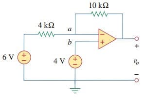
For the op amp circuit in Figure.(4), calculate the output voltage vo.
Solution:
We may solve this in two ways: using superposition and using nodal analysis.
■ METHOD 1: Using superposition, we let
![]()
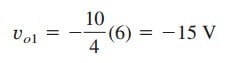
where vo1 is due to the 6-V voltage source, and vo2 is due to the 4-V input. To get vo1, we set the 4-V source equal to zero. Under this condition, the circuit becomes an inverter. Hence the Equation.(2) in ‘Inverting Op Amp‘ gives
 To get vo2, we set the 6 -V source equal to zero. The circuit becomes a noninverting amplifier so that Equation.(3) applies

Thus,
![]()
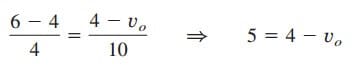
■ METHOD 2: Applying KCL at node a,

But va = vb = 4, and so
 or vo = –1 V, as before.


