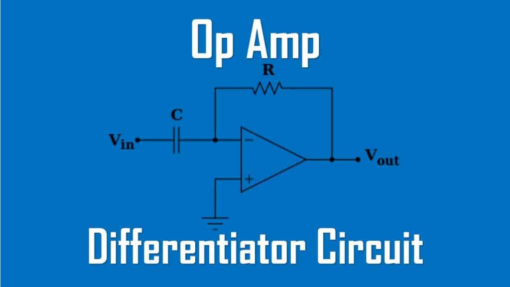
Op Amp Differentiator Circuit and Equation
Differentiator has the same logic as the integrator. We only need to switch the capacitor position with the resistor, and vice versa.
Op Amp Differentiator Circuit
Summary,
A differentiator is an op amp circuit whose output is proportional to the rate of change of the input signal.
In Figure.(1a) in the “Integrator Circuit“, if the input resistor is replaced by a capacitor, the resulting circuit is a differentiator, shown in Figure.(1) below.

Applying KCL at node a,

But

Substituting these in Equation.(1) yields
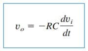
showing that the output is the derivative of the input. Differentiator circuits are electronically unstable because any electrical noise within the circuit is exaggerated by the differentiator. For this reason, the differentiator circuit in Figure.(1) is not as useful and popular as the integrator. It is seldom used in practice.
Read also : three-phase ac circuit
Op Amp Differentiator Circuit Example
Sketch the output voltage for the circuit in Figure.(2a), given the input
voltage in Figure.(2b). Take vo = 0 at t = 0.

Solution:
This is a differentiator with
![]()
For 0 < t < 4 ms, we can express the input voltage in Figure.(2b) as

This is repeated for 4 < t < 8 ms. Using Equation.(2), the output is obtained as
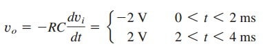
Thus, the output is as sketched in Figure.(3).


