Different Types of Relays – Explanation, Construction, Operation
Types of relays depend on their constructions, applications, functions, and work principles.
Relay is an electrical switch, it means it is a switch controlled by electricity. This switch can be ON or OFF by applying a voltage signal or pulse. For example, we can use the I/O pin of a microcontroller connected with a small LED to switch it ON or OFF.
It will be a different story when we want to use more than 5W LED or light bulb in our home. Since a common microcontroller only produces 5V voltage pulse with low current, it won’t be enough.
This is where relay will be used and of course it is very easy. Relay is capable of delivering higher voltage and higher current. When dealing with the electrical home application, PLC, industrial, or automotive sector we will find several types of relays so often.
What is Relay and Types of Relays
Not only used for electrical switching application, relay can be used for electrical protection application. Since it is able to protect and to switch a circuit, it is an essential electrical component for control circuits.
This is why we will face many types of relays.
Even though there are several constructions for relay, it is basically the same with other switches. Relay also uses the Normally Open (NO) and Normally Close (NC) state for its operation.
The only different thing about relay with physical switch is we only use electricity to control electrical circuits. We only need to use low voltage to trigger the relay which is connected to a higher voltage circuit.
This is why a relay is very safe to control a high voltage circuit since it isolates low voltage circuit (control) with high voltage circuit (load) completely.

We will learn everything about the types of relays here along with their constructions and applications.
Types of Relays : Construction
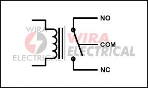
A basic relay has five terminals:
- NO contact terminal
- NC contact terminal
- Common (COM) terminal
- 2 coil terminals
For better understanding, observe the actual relay’s terminals below:

Keep in mind that the relay above is the most basic example.
If we want to observe what is inside the relay above, we can observe the picture below:

Now we will learn each of its terminals.
Coil Terminals
This is where we connect the input circuit or control circuit. We will apply low voltage to the coil to change the relay’s state.
In other words, this is where we control the switching state of a relay. We can energize or de-energize the relay’s coil with AC or DC voltage depending on its type.
The coil will either pull or push the armature, make it either NO or NC contact.
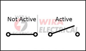
NO Terminal
NO terminal is used for a load circuit terminal which remains in “Normally Open” state when coil is not energized (not active).
The relay will change to a closed circuit with COM terminal when the coil is energized. It will remain in a closed state until the coil is de-energized.

NC Terminal
NC terminal is used for a load circuit terminal which remains in “Normally Close” state when coil is not energized (not active).
The relay will change to an open circuit from the COM terminal when the coil is energized. It will remain in an open state until the coil is de-energized.
COM Terminal
The COM or Common terminal is where we connect the end of the load circuit.
We connect one point of a load circuit to either NO or NC terminal and connect the end of that load circuit to the COM terminal.
Read also : types of sensors
Types of Relays : Poles and Throws
When learning and using a relay we need to know how much it has poles and throws.
Poles
Pole is the dynamic part of a switch. When we want to close or open a circuit, this is the moving part to do it.
We can say poles represent how many switches we can control.
Throws
Throw is the steady part of a switch.
- If a pole and throw are connected to each other, it will produce a closed circuit.
- If a pole and throw are disconnected from each other, it will produce an open circuit.
We can say throws represent how much circuits we can control.

Single Pole Single Throw (SPST) Relay
Single pole means we only control one switch, either ON or OFF.
Single throw means we only control one circuit, either open circuit or closed circuit.

Single Pole Double Throw (SPDT) Relay
Single pole means we only control one switch, either ON or OFF.
Double throw means it has two different conditions or two different electrical circuit paths.
When the coil is not energized, the COM is connected to the first path (NC) and disconnected from the second path (NO).
When the coil is energized, the COM is connected to the second path (NO) and disconnected from the first path (NC).

Double Pole Single Throw (DPST) Relay
Double pole means we can control two switches as two fully isolated circuits.
Single throw means it only controls between NO or NC of these two circuits.
As example, if we use a DPST-NO then:
When the coil is not energized, both circuits are in NO state, open circuits.
When the coil is energized, both circuits are in close circuits.

Double Pole Double Throw (DPDT) Relay
Double pole means we can control two switches as two fully isolated circuits.
Double throw means each pole can change between two states: open or close circuit for two different positions.
DPDT relay is two SPDT relay combined together but both relays work simultaneously.

Types of Relays : Form
Sometimes you will find Form A relay, Form B relay, etc when reading about electrical things using a relay. These types of relays thing is not much different from “pole and throw” configuration.
Form A Relay
Form A is a relay with SPST-NO (Normally Open) configuration. It makes a circuit either open or close connection.

Form B Relay
Form B is a relay with SPST-NC (Normally Close) configuration. It makes a circuit with either close or open connection.

Form C Relay
Form C is a relay with SPDT configuration.
Form C is also known as BBM or Break-Before-Make. It means this relay will Break its NC connection and Make close connection from the second throw when energized.
Summary:
- When the relay is not energized the pole will connect with the first throw.
- When the relay is energized the pole will disconnect from both throws and then connect with second throw

Form D Relay
Form D is also a relay with SPDT configuration.
Form D is NO with the first pole and NC with the second pole when not energized.
This is known as MBB or Make-Before-Break. It means this relay will Make close connection with the first throw and Break connection from the second throw when energized.
Summary:
- When the relay is not energized the pole will connect with the second throw.
- When the relay is energized the pole will connect with the both throws and then only connect with the second throw.

Types of Relays : Operation and Application
Based on their operations and applications, we can classify types of relays into many groups. Below you will find types of relays based on their applications and operation principles.
1. Electromechanical Relay
Electromechanical relay or EMR is the most basic among the types of relays. Its main components are:
- A mechanical dynamic contact (pole), known as armature.
- An electromagnetic coil.

Its operation principle is very simple and straightforward.
When we energize the coil, it will produce a magnetic field. This magnetic field will attract the armature. When the coil is not energized, the armature will move to its original position.
We can use this relay for AC or DC circuits depending on what is the purpose of this relay.
The difference between AC and DC relay is the use of a freewheeling diode on a DC coil for protection against EMF and sudden de-energized coil.
Since it is a coil, the polarity of our source doesn’t matter but we need to take caution for its back EMF.
The disadvantage of an EMR relay is its armature produces an arc when the coil is de-energized, when the armature breaks its connection from the contact.
This arc will reduce the relay’s lifespan and increase the resistance over time.
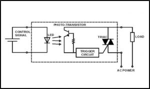
2. Solid State Relay
Solid State Relay or SSR for short is not constructed from mechanical parts.
This relay is made from semiconductor material just like diodes and transistors. Its switching ability is performed by semiconductor devices such as thyristor, MOSFET, IGBT, BJT, or TRIAC.
This device needs less power to consume for the control circuit to control the load circuit with much higher power. Hence, this relay has higher power gain than an electromechanical relay (EMR)
Even though there is no mechanical part to operate its function, it still works very well on isolating the low voltage control (input) circuit from the high voltage load (output) circuit.
This isolating principle is achieved by using an optocoupler inside it.

When the voltage pulse is applied to the SSR, its infrared light is emitted. On the other side, a photosensitive receiver made from semiconductor material is ready to receive the infrared signal.
Later, this signal will be processed into an electrical signal and change the switch state of the high voltage circuit.
Because everything is operated by semiconductor material and electrical signal processing, SSR switching speed is high and power consumption is lower than EMR.
Obviously, because there is no physical contact, its lifespan is longer.
The disadvantage from using SSR is its voltage drop across the semiconductor material is wasted into heat energy.
The advantage from using SSR is its lifespan is expected to be higher because of the lack of mechanical moving parts. SSR also produces less noise.
There are some types of relays for SSR type:
Photo Coupled SSR
This SSR has a semiconductor photosensitive device for its switching operation. The control signal will be emitted by the LED and the photosensitive device enters conduction mode right after the light from the LED is detected.
The isolation level of this photo coupler is considered high level compared to transformer coupled SSR because it fully operates using electrical signals.
Transformer Coupled SSR
At first, the control circuit will produce DC current and convert it into AC current with the help of its DC-AC converter.
This AC current will flow through the primary side of the transformer and the current is stepped up to control the solid state device such as TRIAC and triggering the circuit.
The isolation level of this SSR depends on the transformers’ ability and design.

3. Hybrid Relay
From the name implies, this relay is a combination of more than one types of relays. Hybrid relay is a combined EMR and SSR relay.
Remember that both EMR and SSR relays has their own disadvantage:
- EMR produces arcs when breaking connections.
- SSR has its voltage drop wasted into heat energy.
Combining these two will get rid of their disadvantages.

Inside the hybrid relay is EMR and SSR connected in parallel.
The operation sequence is:
- First, the low voltage control circuit turns ON (energizing) the SSR.
- The high load current is taken by SSR.
- Because there is no mechanical part, the arc problem is gone.
- Second, the low voltage control circuit turns ON (energizing) the EMR.
- Since the coil is energized but not carrying high load current, there is no arc produced by armature contact.
- After some time after EMR contact is attracted, the control circuit no longer controls the SSR.
- As long as EMR is energized, it controls the load current without any power loss wasted into heat energy.
4. Reed Relay
Among the types of relays, this relay has the most simple construction.
Reed relay uses electromagnetic field working principle. This relay is constructed from an electromagnetic coil, a reed switch, and a diode for back EMF protection.
Reed switch is a switch made from two metallic blades made from ferromagnetic material. These blades are sealed inside a glass tube filled with inert gas.
The electromagnetic coil is wound around the reed switch where the switch acts as the armature. Both the ends of the reed switch are connected to input and output of the circuit.
This relay uses the same principle as electromechanical relays (EMR).

When we energize the reed relay, the metallic blades will attract each other and make a close circuit connection. Unlike the EMR, this relay has much smaller contact and lower mass.
The inert gas can extend its lifespan.
The disadvantage of this reed relay is the arc produced when making contact. However its switching speed is better than EMR because of its smaller contacts and different medium.
You may find this relay is quite unreliable because there is a possibility that the contacts are still in close circuit even after the coil is not energized anymore.
We can solve this problem by installing impedance such as resistor or ferrite connected series between relay and capacitance. This can reduce inrush current hence we avoid any arc produced in the relay.
5. Electrothermal Relay
Electrothermal relay is also known as thermal relay for simplicity.
It is quite similar to reed relay where this relay uses two bimetallic metals which both have different thermal expansion coefficients.

When we apply voltage to it, the current will flow through the conductor and produce heat.
This heat will expand the bimetallic strips. Due to different coefficients, one of the strips will bend and make close connections with the other strip.
Thermal relay is effective to be used for electric motor protection.
6. Polarized Relay
From the name implies, this relay has high sensitivity to our current’s direction. This time we will use DC voltage to energize this relay unlike electromagnetic relay (EMR) where we can use either AC or DC.
Polarized relay uses the combination of a permanent magnet and an electromagnet. The permanent magnet will be the armature while the electromagnetic will act as a coil to attract the permanent magnet armature.
This is why this relay is called polarized relay because the polarity will determine the permanent magnet armature position.

We will not use spring to pull the contact. We just need to apply current in reverse direction to make the armature moves to another position.
If we reduce the current until the electromagnetic force is less than the permanent magnet, the armature will return to its original position.
When there is no current, the armature will be either in the left or right position because there is no absolute neutral in the magnetic field.
7. Latching Relay
Latching relay has latching or time delay to prevent its state changes immediately after energization. This relay will maintain its state a while after being energized.
From this characteristic, the latching relay is very effective for limiting power consumption and dissipation.
To achieve this, the latching relay has a permanent magnet inside it. When the voltage is applied to the coil (energizing the relay), the magnet will hold the contact.
Since it is a permanent magnet, we don’t need energy to hold the contact.
This mechanism will save some energy because the contact position will remain at its latest position after voltage is no longer applied to the coil.
Latching relays can be made from single or double coils. This is easier because we will apply the voltage to the second coil instead of applying reverse current to the first coil.
Observe the one coil latching relay operation below:
1. First we have a one-coil latching relay with NO position.
2. We energize the coil with current from the top side. The contact will change from NO to NC position.

3. We stop energizing the coil but the contact will stay at the same position (NC).

4. We energize the coil with current from the bottom side. The contact will change from NC to NO position.

5. We stop energizing the coil but the contact will stay at the same position (NO) and repeat from Step.(1).
Observe the two coils latching relay operation below:
1. First we have a two-coils latching relay with NO position.

2. We energize the first (left) coil with current from the top side. The contact will change from NO to NC position.

3. We stop energizing the first coil but the contact will stay at the same position (NC).

4. We energize the second coil with current from the top side. The contact will change from NC to NO position.

5. We stop energizing the second coil but the contact will stay at the same position (NO) and repeat from Step.(1).
8. Buchholz Relay
This relay uses gas to operate its switch. Unlike other types of relays we have read until now, this relay is used for detector and automatic protection purposes.
This relay is able to detect internal minor faults to prevent major faults before it is too late.
You will find this mostly on the high power transformer as its protection system, installed in a chamber between the tank and conservator.
Among the types of relays, Buchholz relay is used only for oil immersed relay majorly used for power transmission and distribution system, especially for the transformer’s side.

Observe the illustration above to understand what is its operation principle:
- A minor internal fault has occurred inside the transformer, its oil surface will fall caused by accumulation of the gas.
- The float will tilt and contacts (mercury) form a closed connection.
- This closed connection will connect the relay to the alarm circuit.
- The alarm circuit is activated.
- The operators can solve the faults quickly.
Every time a major fault occurs in the transformer (short circuit, grounding faults, etc), the pressure inside the tank is increased rapidly because the level of the oil is reduced rapidly.
The oil then moves to the conductor and causes the lower side flap valve to get deflected. This will close the mercury switch contact and the trip circuit is triggered.
From this operation, the transformer will get disconnected from the supply source.
9. Overload Protection Relay
From the name implies, this relay is used for protection against overload conditions, especially for overcurrent in electrical circuits and motors.
We can find several types of relays for this purpose such as interchangeable heater bimetallic, fixed bimetallic strip type, etc.
We all know that every electric motor has a current limit to prevent its parts being damaged. For this matter, electric motors need to be disconnected from any source when overcurrent occurs.
Before cutting the connection, we need a device to automatically detect this overcurrent as fast as possible. This is where overload detector equipment is installed such as heat operated relay.
This heat operated relay is constructed from a coil which heats the bimetallic strip. This heated strip will release the spring to operate the contact which is connected series with the coil.
The coil will get de-energized when the overcurrent is detected in the load by the detector.
Aside from that, this overload protection relay can detect the motor winding temperature, hence the motor gets protected properly and accurately.

10. Inverse Definite Minimum Time Relay (IDMT relay)
From the name implies, this relay works inversely of “something” in the circuit. The IDMT relay generates a definite time-current characteristic with inverse value.

What is the inverse value of operating this relay?
Simply to be told:
- The higher current fault detected in the circuit, the smaller operating time of the relay.
- The lower current fault detected in the circuit, the higher operating time of the relay.
This is what we call inversely proportional faulty currents with respect to operating time.
This can be done with the help of a magnet core that gets saturated when the current is slightly higher than the pickup current.
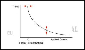
What is pickup current?
Pickup current is the value of the current where the actuating value or fault current initiates the relay.
11. Differential Relay
Differential relay uses “differential of values” when controlling signal or operating the relay.
Differential relay is initiated when the difference of the phasor between two or more same electrical parameters exceeds a determined value.
For example, a current differential relay will be initiated when the entering current and leaving current have difference between its magnitude and phase in a protected circuit.
When the relay is in normal condition, it means both entering current and leaving current have equal magnitude and phase.
As soon as the faults occur, the magnitude and phase between these two don’t have equal values.
The relay is connected in some way so that the entering current and leaving current flow through the relay’s operating coil.
The way it is constructed, the coil will be energized when fault occurs caused by the “difference” we mention above.
The relay will activate the circuit breaker and make the circuit trip.
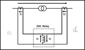
From the illustration above, we understand that a differential relay has two CT (center-tapped) connected to two sides of a power transformer.
The relay will compare the current from both sides and if there is any difference then the relay will start operating.
Of course there is voltage differential relay, its operation is also the same with current differential relay but using voltage as its parameter.


This site is really amazing,l get to read on some relays l never know about as a student of electrical and electronics engineering, it is important to have a full knowledge of such electrical and electronics devices.