Looking for a way to charge a capacitor? If so, then your simplest solution to do it is the RC circuit. We will also find the capacitor charging equation.
This type of circuit is quite simple. Connecting the resistor, capacitor, and voltage source in series will be able to charge the capacitor (C) through the resistor (R).
Time Delay or Time Constant RC Circuit
Before moving on to the RC charging circuit and capacitor charging formula, it is wise for us to understand this term, called Time Constant. We will find this time delay or time constant in every electrical and electronic circuit.
Shortly, there will be some “time-delay” in the electrical circuit between input terminal and output terminal when the circuit is supplied by voltage or signal in direct current (DC) or alternating current (AC).
Moving on, this Time Constant represents the first-order time response of the circuit supplied by signal or voltage. This time constant value is dependent on the reactive components, such as capacitor and inductor in the circuit.
We will find the time constant a lot if we try charging a capacitor.
The units of Time Constant is Tau, with the symbol of – 𝜏
First, let’s assume that we have a circuit with an “empty” capacitor. We may call this a “discharged” capacitor. Then we apply a DC voltage to the circuit and the current is starting to flow. This current is drawn by the capacitor and we call it a “charging current”.
The capacitor is starting to “charge up” as long as the DC voltage source is applied. As soon as the voltage is reduced, the capacitor starts to do “discharging” with the direction opposite to the voltage source.
You may wonder “why is it like that?”.
Well, if we try to search it in Google, we will find the answer right away, provided by Wikipedia. But let us write it here so you don’t need to open a new tab.
With a simple explanation, a capacitor is a device which provides capacitance to the circuit. The physical form of a capacitor consists of two electrical conductors. It may be a pair of metallic plates or surfaces separated by a dielectric medium.
There is an equation for calculating the stored electrical charge between the conductor plates, it is:
![]()
This charging and discharging of a capacitor needs time to be done. This is where we use the term “Time Constant” for calculating the required time.
This will also act as the capacitor charging formula.
Summary, the Time Constant is the time for charging a capacitor through a resistor from the initial charge voltage of zero to be around 63.2% of the applied DC voltage source. Time Constant is also used to calculate the time to discharge the capacitor through the same resistor to be around 36.8% of the initial charge voltage.
The RC circuit is formed from a series connection of a resistor, a capacitor, and a voltage source like mentioned above. The capacitor will gradually charge up its charge voltage until the value is the same with the voltage source in an ideal assumption.
The interval time for the capacitor for full charging is also known as transient response time 𝜏. We can find the value from the product of the resistance and capacitance. Hence,
![]()
Where:
𝜏 = time constant, measured in seconds (s)
R = resistance, measured in ohm (ohm)
C = capacitance, measured in Farads (F)
Capacitor Charging RC Circuit
In order to charge a capacitor with the simplest method, we will use a capacitor (C), a resistor (R), and a DC voltage source. We connect these components all in series with the addition of a switch.
At the initial time, or time zero, the switch is closed and the capacitor is starting to charge up. The capacitor will charge up until its voltage reaches the source voltage.
When the switch is closed, the capacitor will try to maintain its variable values before the transition state of the switch. This value will be used as an ‘initial value’ when we do the circuit analysis.
Its steady state or final value will be in infinite time where the value is not changing anymore.
Let’s assume that the capacitor is at the initial or starting point when the capacitor is “empty” or “fully-discharged”. At this state, the capacitor acts as a short-circuit, and the current is flowing at maximum value.
Its final state or “steady-state” is when the capacitor is “fully-charged”, there is no current flowing and the capacitor acts as an open-circuit.
What do we need to find next?
We need the “time-constant” to calculate how long the capacitor needs to be fully-charged. This variable is also important to calculate how much the capacitor is charged after a while.
In the RC circuit we get the time-constant (tau – 𝜏), from the multiplication between resistance R and capacitance C. One thing to note, one time-constant is the amount of time for the capacitor voltage to reach 63% closer to the voltage source.
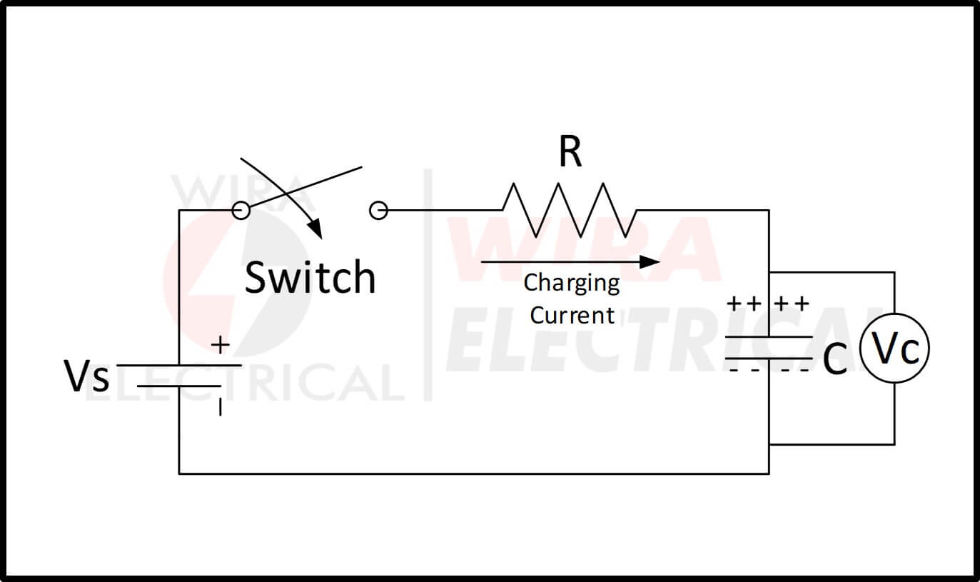
Now, let’s analyze the equation for the process of charging a capacitor from the figure above. Assume that the capacitor (C) is in “fully-discharged” condition after we open the switch (S). It means there is no voltage in it.
We call this first step as the initial conditions, where t = 0 s, i = 0 (open circuit), and q = 0 (no voltage charge, fully-discharged).
When we close the switch, the time begins at the timestamp t = 0 and the current is starting to flow to the capacitor through the resistor.
The charge voltage in the capacitor is still zero (Vc = 0) because it was fully-discharged first at t = 0. In this state, the capacitor is a ‘short-circuit’. The total current is restricted only by the resistor.
With the help of Kirchhoff’s voltage law (KVL), we can calculate the voltage drops in the circuit as:
![]()
Now after the switch is closed, the current is flowing freely in the circuit. This current will be called a Charging Current. This current can be measured using the simple Ohm’s law as:
![]()
Equation for Capacitor Charging RC Circuit Graph Analysis
The rise of the capacitor voltage and the fall of the capacitor current have an exponential curve. It means, the values are changing rapidly in the early and settling down after a set amount of time.
As we mentioned above, for every one time-constant (1𝜏), the value will be 63% closer to the desired value.
Now let’s take a look at the graph of capacitor charging voltage and capacitor charging current below:
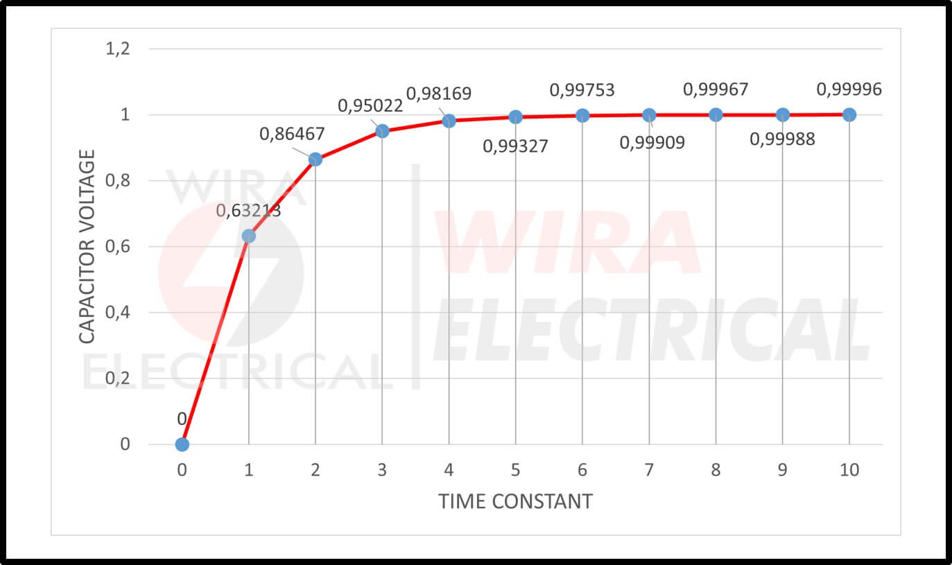
The graph above is explaining how the voltage of the capacitor increased over time until it reached the voltage source. The slope of the beginning is steeper, because at that time the capacitor is starting to charge up with full current.
More time passes and the slope is starting to get its stable curve. The charging rate is slower when the voltage difference between the capacitor and the source thin out.
The potential difference between the plates increases over time with the actual required time for the electric charge of the capacitor to reach 63.2% of its maximum possible voltage (voltage source).
From the curve above, you will find the Time Constant – 𝜏 again.
This voltage point 0.63Vs or 63.2%Vs stands for one time-constant or 1𝜏.
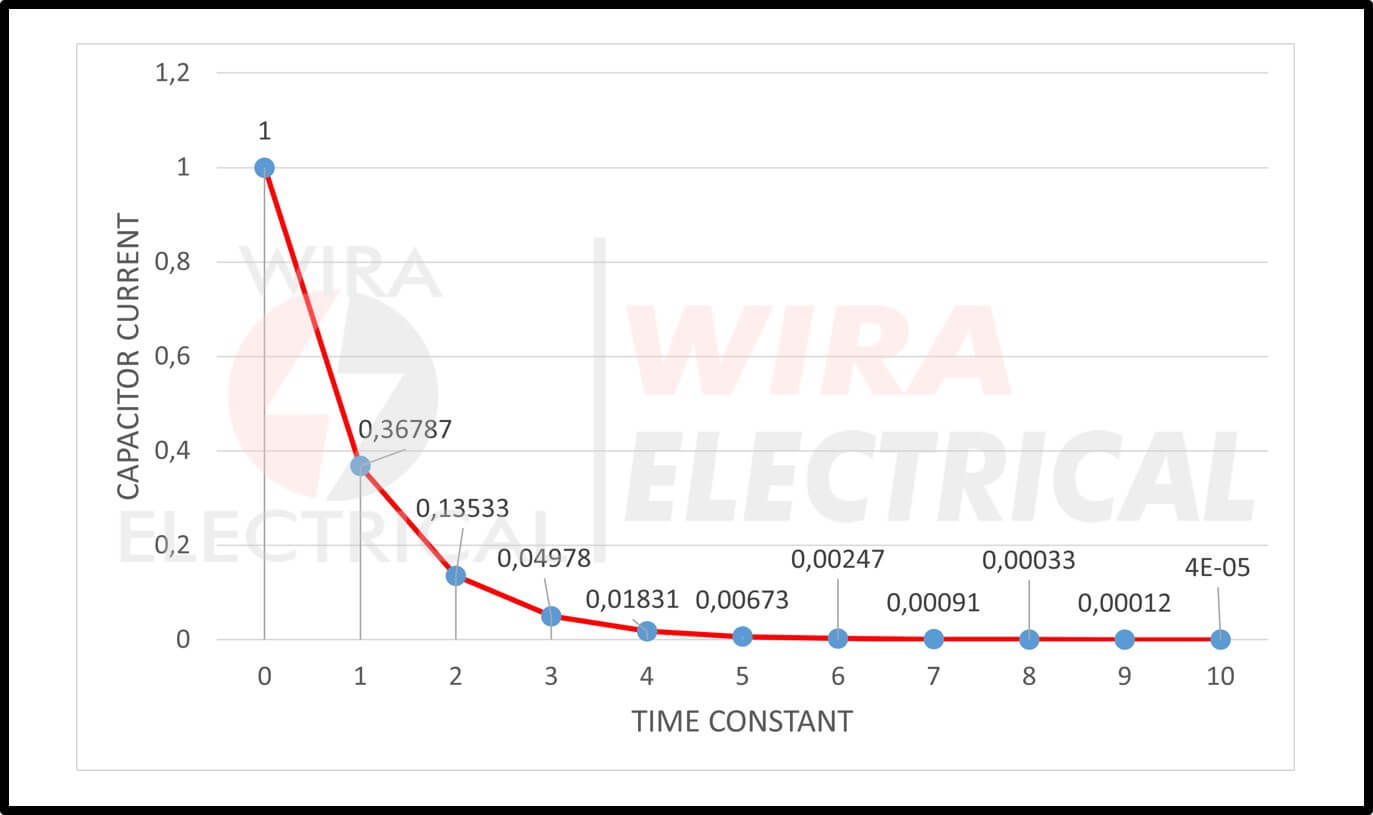
The curve above shows us the slope of the capacitor charging current. The values can be calculated from the equation for capacitor charging below.
Comparing it to the voltage curve, it is the opposite. As more time is taken when charging, the current in the circuit is decreasing until it reaches zero.
Why?
Scroll a little up and you will find the answer from the voltage perspective. As the voltage difference between capacitor and source is decreasing, the required current to charge the capacitor is also decreasing.
More charged capacitor means more resistance in the circuit, because a fully-charged capacitor acts as an open-circuit.
The capacitor is reaching its limit when the time taken is higher than the ten time-constant (5𝜏). From the equation for capacitor charging, the capacitor voltage is 98% of voltage source.
This time, the capacitor is said to be fully-charged and t = ∞, i = 0, q = Q = CV.
When the time is greater than 5𝜏, the current decreased to zero and the capacitor has infinite resistance, or in electrical terms, an open-circuit. The capacitor voltage is Vc = Vs.
Below we will start using the capacitor charging formula.
Capacitor Charging Equation
If looking at the curve is a little too hard, we can calculate the time constant with an easy equation for capacitor charging. Basically, we can express the one time-constant (1𝜏) in equation for capacitor charging as
![]()
Where:
𝜏 = time-constant
R = resistance (Ω)
C = capacitance (C)
We can write the percentage of change mathematical equation as capacitor charging equation below:
![]()
Where:
e = Euler mathematical constant (around 2.71828)
t = time taken, in seconds
𝜏 = time-constant, in seconds
After the time reaches one time-constant or 1𝜏, the percentage of change from initial value to its desired value using the capacitor charging formula is:
![]()
After the time reaches two time-constant or 2𝜏, the percentage of change from initial value to its desired value using the capacitor charge formula is:
![]()
After the time reaches five time-constant or 5𝜏, the percentage of change from initial value to its desired value using the equation for capacitor charging is:
![]()
After the time reaches ten time-constant or 10𝜏, the percentage of change from initial value to its desired value using the capacitor charging equation is:
![]()
Those percentage of change values above clarify the values we put in the table in the next section.
We know that the voltage source V is responsible for charging a capacitor. The capacitor voltage Vc can be measured from the division of Q/C. The capacitor voltage Vc during any time at charging process can be expressed as:
![]()
Where:
Vc = voltage across the capacitor
Vs = voltage source
t = time taken since the voltage source is connected to the resistor and capacitor
RC = the time-constant 𝜏 of the RC circuit
There are two parts of periods in the two graphs above. We call them:
- Transient state
- Steady-state
The transient state is the period when the variables of the system or circuit have been changed over time. The system is still in a transient state as long as the system has not reached the steady-state.
The required time for a circuit changing from one steady-state to another steady state is called transient time.
Steady-state is the period when the variables of the system or circuit have reached stable condition. The variables are not changing anymore in time.
Looking from the graphs we can conclude when the circuit is in a transient state and steady-state, even if we remove the text explanation above the curve.
The transient period starts from the initial zero time until 4 time-constant (5𝜏). The capacitor voltage in this RC circuit has reached about 98% of the most possible maximum voltage, the voltage source.
Summary, the time required for the RC circuit to charge the capacitor until its voltage reaches 0.98Vs is the transient state, about 4 time-constant (4𝜏).
After the time has been reached 5𝜏, it is said that the capacitor is in steady-state. The capacitor is fully charged and the capacitor voltage (Vc) is equal to the voltage source (Vs).
Because the capacitor is fully-charge, the capacitor acts as an open-circuit. Hence, there is no current flowing in the circuit anymore.
The curve of the graphs has exponential values. It means the capacitor voltage never reaches 100% of the voltage source in a practical condition.
The time after 5𝜏 is still the capacitor steady-state period, where the capacitor voltage is about 99.3% voltage source. We can still say the capacitor is fully charged, though.
Universal Time Constant Formula
We can multiply the percentage of change we got with the difference between the initial value and desired value. We can use this universal formula to determine the time is taken, the voltage and current values, and also the percentage of change:
![]()
Where:
Final = Desired value or the value after infinite time
Initial = Initial value of the variable
e = Euler’s constant number (about 2.71828)
t = Time in seconds
𝜏 = Time constant in seconds
This equation is also considered to be a capacitor charging equation.
Let’s try to apply the equation above with the circuit below.
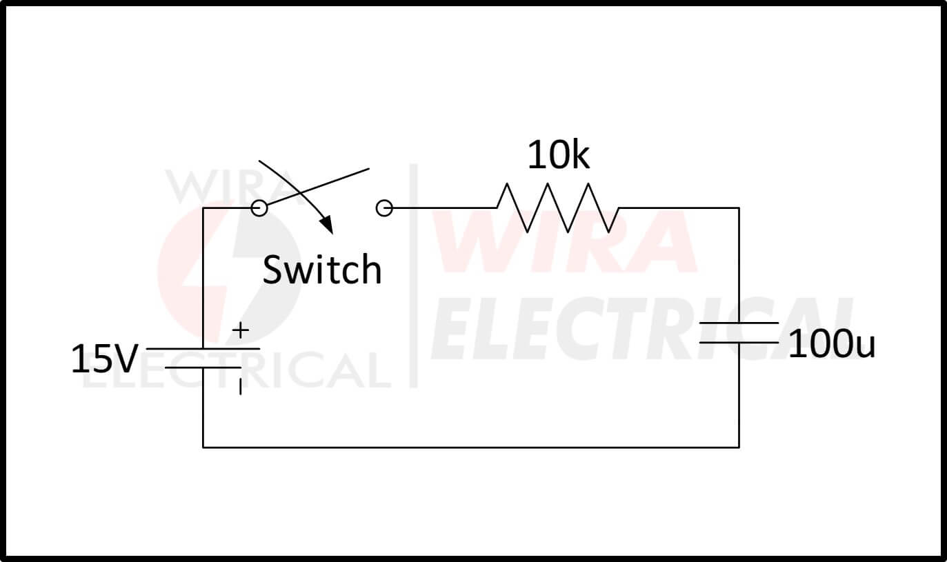
The RC circuit above has a 10kΩ resistor, a 100 uF capacitor, and a voltage source 15V. We know that time-constant (𝜏) is the multiplication of resistance (R) and capacitance (C), hence

Let’s assume that the capacitor is fully discharged, then the initial value is 0 volt. Our desired value is 15V since we want to fully-charge the capacitor.
Then the mathematical equation is:

Let’s try to set the time taken into 7.25s. Hence, 7.25 seconds after the switch is closed, the capacitor voltage value has risen by:

It means we will charge the capacitor up to 14.989 volts after 7.25s.
Not only that, but we can also use this equation for capacitor charging to calculate the current since the equation is universal. Let’s try it now.
Keep in mind, there is characteristic for the capacitor for either charged or discharged:
- The discharged capacitor acts as a short-circuit, hence the initial current is maximum.
- Charged capacitor acts as an open-circuit, hence the final current is minimum.
From these characteristics, we can conclude that:
- Initial current : I = V/R = 15V / 10kΩ = 1.5mA
- Final current :0A
Using the same t = 7.25s, thus the current after 7.25s is:

Take note that the value of the current is negative. It means that the current is decreasing over time from the beginning until 7.25s. The initial current is 15mA, while the difference after 7.25 is (-1.4989 mA).
Summary, we will have (1.5mA – 1.4989mA) 0.0011 mA or 1.1 uA after 7.25s.
Or maybe we don’t need the time-constant equation to find the final current. We can just use the simple Ohm’s law using the difference between the initial and final voltage, divided by the resistance.
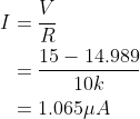
It is convenient that the equation for capacitor charging goes well with other basic laws like Ohm’s law.
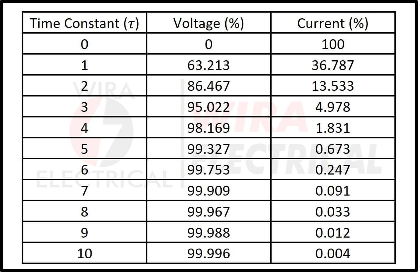
Capacitor Charging Equation Table
We can turn the capacitor charging graphs and the equation for capacitor charging into one simple RC charging table below.
Capacitor Charging Equation Examples
Let’s apply the equation for charging a capacitor into some practice. Find the time constant 𝜏 for the RC circuit below.
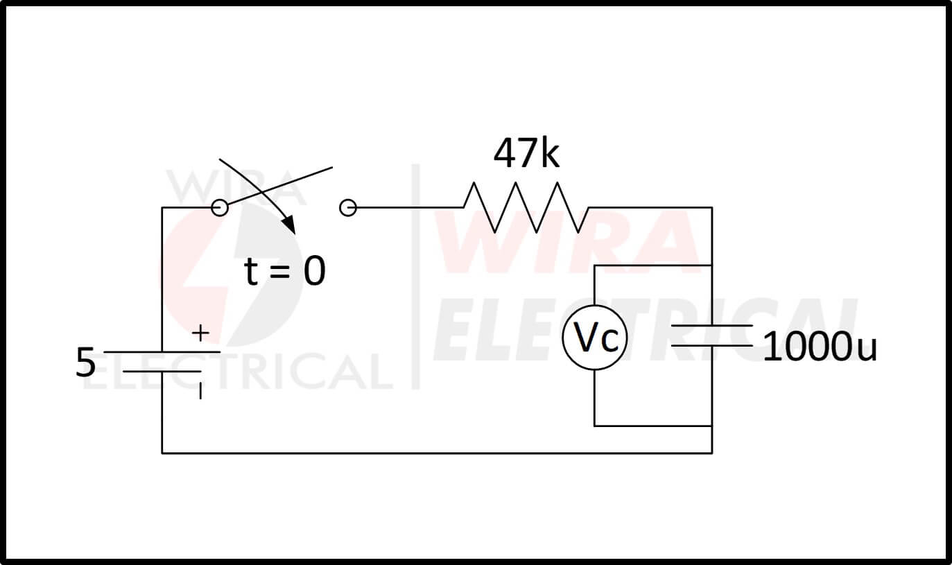
We can use the time constant formula above, where 𝜏 = R x C, measured in seconds.
Hence, the time constant is 𝜏 = R x C = 47kΩ x 1000uF = 47s.
a) Calculate the capacitor voltage at 0.7 time constant.
At exactly 7𝜏, the capacitor voltage Vc is equal to 0.5Vs.
Hence,
Vc = 0.5Vs = 0.5 x 5V = 2.5V
b) Calculate the capacitor voltage at 1 time constant.
At exactly 7𝜏, the capacitor voltage Vc is equal to 0.63Vs. Hence,
Vc = 0.63Vs = 0.5 x 5V = 3.15V
c) Calculate the time taken for the capacitor to be fully-charged.
We have read the graph above that we need 5𝜏 to charge the capacitor fully. We already got the time constant from point ‘a’.
Hence,
5𝜏 = 5 x 47s = 235s
d) Calculate the capacitor voltage after 100s.
The formula for capacitor voltage is Vc = V(1 – e(-t/RC)).
Hence,

Summary of Equation for Capacitor Charging
From the long explanation above, we can summarize the equation for capacitor charging into the steps below:
- Find the time-constant (𝜏 = R x C).
- Set the initial value and the final value.
- Use the universal time-constant formula and put every variable obtained in the equation.
- Solve the equation.
- You can either calculate the time taken until the final value is reached or calculate the final value after a set amount of time.
- Now we have seen the use of the equation for capacitor charging.
Frequently Asked Questions
Let’s review the most frequently asked questions about equation for capacitor charging below:
How do you calculate the charge on a capacitor?
The electric charge Q in a capacitor (measured in Coulombs or C) is equal to the product of the capacitance C of the capacitor (measured in Farads or F) and the voltage V across the terminal (measured in volt or V). Mathematically, Q = C x V. If C = 10uF and V = 10V, then Q = 10u x 10 = 100u Coulombs.
What is the charging of capacitors?
If we connect a capacitor, a resistor, and a voltage source in series, the capacitor will be charged up until its voltage value is equal to the voltage source. Charging of capacitors means we store energy in the capacitor in electric field form between the capacitor plates.
How long does it take to charge a capacitor?
About 10 time-constant.
One time-constant equal to the product of the resistance and capacitance in the RC circuits. The capacitor will be charged about 99.995% of the voltage source.
What happens when a capacitor is fully charged?
The capacitor will stop charging if the capacitor is “fully-charged”. At this time, the current will stop flowing in the circuit because the capacitor acts as open-circuit. The capacitor voltage Vc is equal to the Vs and the voltage source connection is disconnected.
A discussion of the calculation for discharging capacitor would make this more complete. Students often find discriminating between the charge and discharge calculations difficult. Otherwise, this is terrific! Thanks for the good work.
Ron Felix
Electronics Instruction
Advanced Manufacturing Program Support
Bellingham Technical College
Well explained ,have already passed the exam