Diode as Switch and Junction Simple Explanation
The diode is a popular electrical component that has a wide variety of applications. One of its applications is a diode as a switch.
A diode is a two-terminal electrical component constructed by a PN junction to give it the ability to work at two modes just like a switch.
Basically:
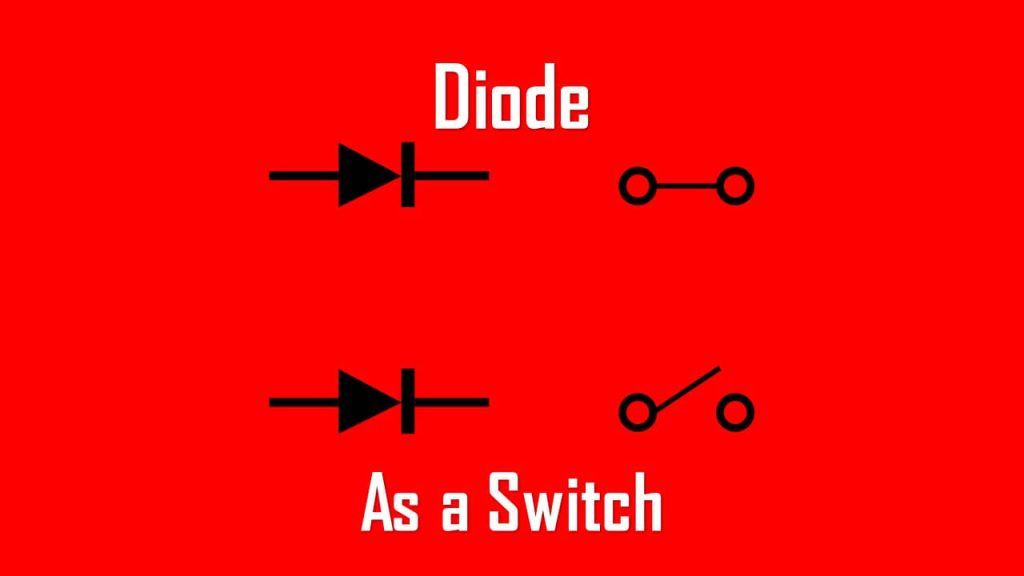
- When the diode is forward-biased, it acts as a close circuit or short circuit.
- When the diode is reverse-biased, it acts as an open circuit.
The forward biased is the ON state, while the reverse biased is the OFF state.
The diode becomes reverse biased and functions as an open switch if a predetermined voltage is surpassed because the diode resistance increases. A closed switch is created when the applied voltage falls below the reference voltage because the diode resistance decreases and the diode becomes forward biased.
How do we prove it?
We will find the answer below.
Diode as a Switch
Why is a diode as a switch more preferred than a mechanical switch?
There are several advantages to using diode over a mechanical switch:
- Diode will not be affected by oxidation of metals over time, unlike a mechanical switch
- We don’t need movable contact or parts like what we find in a mechanical switch
- There is a limit to operating the mechanical switch, whereas the electrical switch is almost limitless
- The mechanical switch will eventually break down compared to the diode which last longer
Diode Acts as a Switch
The basic operation of a diode is when a voltage is applied to the anode, the diode is forward biased and acts as a closed circuit.
Otherwise, when a voltage is applied to the cathode, the diode is reverse biased and acts as an open circuit.

This electronic component is able to block the reverse flow of current as long as the voltage is applied to the cathode and still within the breakdown voltage.
A diode is constructed from a PN junction with the:
- P-region is lightly doped and
- N-region is heavily doped
If terminal A gets higher potential than terminal K, the device will be operated in forward biased mode and the current flowing in the direction as shown is called forward current (IF).
This produces a relatively small voltage drop across the device (< 1 V), and can be ignored in ideal condition.
Observe the circuit below where the diode is ON (forward biased) when the voltage is forward biased (applied to the anode), while the diode is OFF (reverse biased) when the voltage is reverse biased (applied to the cathode).

On the other hand, when reverse-biased, it does not let current flow through and a practical power diode will have a small current flowing in the reverse direction called the leakage current.

Switching Characteristics of Diode
Utilizing a diode as a switch does not come without any calculation. There will be something called “ringing” if the diode is switched ON and OFF suddenly before its recovery time is achieved.
The oscillation will be generated by the sudden change from forward current to reverse current and vice versa.
Along with the oscillation, the sudden change of current will generate power loss due to the leakage current from switching to suddenly. The higher the leakage current, the greater its loss.
Switching Characteristics of PN Junction Diode
Of course unlike mechanical switch which is able to switch between ON and OFF almost instantly, the diode and other electronic component have something in common:
Transient response
This response occurs when the diode switches from one condition to another condition, lasting for a very short time.
The change from forward bias to reverse bias and vice versa in a short time will cause an effect to the circuit, and often it is ignored by many people.
But before we start learning about the switching characteristic of PN Junction Diode, we will learn a few variables used in the explanation, they are:
- Recovery Time = the time before the diode recovers from the transient state to its steady state.
- Forward Recovery Time (tfr) = the time needed by the diode to switch from reverse biased to forward biased
- Reverse Recovery Time (trr) = the time needed by the diode to switch from forward biased to reverse biased
- Storage Time (Ts) = the time interval when a diode remains in forward biased state (conduction state) even if it is in the reverse biased state.
- Transition Time (Tt) = the time needed by the diode to reach steady state after its change from forward biased to reverse biased and vice versa.
- Charge carrier density, also known as carrier concentration = the number of charge carriers per volume.
- Forward voltage, VF is the voltage drop of a diode across A and K when it is forward biased.
- Reverse current, IR is the current at a specific voltage, which is below the breakdown voltage.
Now we will learn about Reverse Recovery Time (trr), as stated above is the time needed for a diode to go into reverse biased from forward biased. The illustration of the relationship between the time and the voltage is shown below.
The important timestamps are:
- Time 0 to t1 is the steady state of forward bias.
- Time t1 is when there is a sudden change from forward biased to reverse biased.

- Time t1 to t2 is the Storage Time (Ts), the required time to remove the excess minority carrier charge
- Time t2 to t3 is the Transition Time (Tt), the required time to to completely change to reverse biased

- Time t1 to t3 is the reverse recovery time (trr), the overall time needed by the diode to switch from forward biased to reverse biased
- Time t3 and beyond is the steady state of reverse bias.

The reverse recovery time of diode formula is the sum of storage time and transition time.
![]()
It is important to calculate the reverse recovery time. Lower trr indicates it can be switched faster.
If time interval from the maximum reverse current to approximately 0.25 of reverse recovery current (IRR) can be ignored (common case), then the following equation is valid:
And the reverse recovery current
![]()
where QRR is the storage charge.
Keep in mind that there are several factors that can affect the ability of a diode as a switch:
- Diode resistance
- Diode capacitance
- Depletion width
- Doping concentration