Simple Wye Delta Transformations Circuit
If you’ve worked with resistor networks long enough, you’ve probably hit this moment:
The circuit looks simple, but nothing is in series, nothing is in parallel, and every “obvious” step leads nowhere.
This is usually where people either give up—or discover the wye delta transformation.
It’s not flashy. It’s not intuitive the first time. And yet, once you’ve used it a few times, it becomes one of those tools you quietly rely on when circuits stop playing nicely. The payoff is real: fewer dead ends, cleaner analysis, and a lot less guessing.
It is often in an electric circuit where resistors are connected neither in parallel nor in series.
This topic will help us understand about:
- Wye to delta transformation
- Delta to wye transformation
Let’s slow down and unpack it properly.
What Is Wye Delta Transformation, Really?
Most explanations start with definitions. That’s fine, but it misses the motivation.
So first, the purpose.
The wye delta transformation exists to solve a very specific problem:
How to simplify a three-terminal resistor network that cannot be reduced using basic series–parallel rules.
Now the definition.
A delta (Δ) network consists of three resistors connected in a closed loop.
A wye (Y) network consists of three resistors connected to a common node.
What matters is not the shape. What matters is this:
After transformation, the resistance measured between any two external terminals stays exactly the same.
If that condition is met, the rest of the circuit doesn’t “notice” the change. From an analysis point of view, nothing has been disturbed.
Why Engineers Bother Using This at All
You might reasonably ask why we don’t just avoid these networks altogether.
In practice, you can’t.
Bridge circuits, sensor networks, biasing networks, and educational problems all love three-terminal layouts. And once you move into power systems, wye vs delta circuits become unavoidable at a conceptual level.
The transformation gives you back control. Instead of staring at an unsimplifiable mess, you reshape it into something workable. That alone justifies learning it.
The Principle Behind Delta–Wye Conversion (No Magic Involved)
Before jumping on to the transformation and conversion formula, we need to understand:
- Wye network
- Delta network
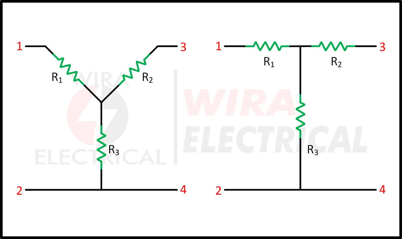
The Wye network has the shape of wye (Y) or tee (T) as shown below respectively.
The Delta network has the shape of delta (Δ) or pi (π) as shown below respectively.

These networks are mainly used for three-phase circuits to achieve desired voltage and current. Not only that, we will likely find these networks in an electrical filter and matching networks.
Of course delta-wye transformation will also help us simplify circuit analysis in a DC circuit.
The delta star conversion technique is derived by equating resistances between terminals using Ohm’s Law and Kirchhoff’s Laws. No assumptions. No approximations.
This is also why the method holds up across IEEE references, IEC-aligned courses, and classic circuit textbooks.
One small warning: because the formulas are exact, arithmetic mistakes matter. Most wrong answers come from bookkeeping errors, not conceptual ones.
Delta to Wye Transformation Formulas
Since the wye network is more convenient to analyze over the delta network, we will start with the delta wye transformation.
We overlap the delta network with the wye network and analyze the equivalent resistance. Since we have to find the equivalent resistance, both wye and delta networks should have equal resistance to each other.
We will compare wye and delta networks and make sure the resistance in the wye (Y) network is equal to the resistance in the delta (Δ) network.
Observe the previous wye circuit below.

The left one is wye (Y) or tee (T) network and the right one is delta (Δ) or pi (π).
The resistance for terminal 1 and 2 for wye network is

\begin{align*}
R_{12}(Y)=R_1+R_3
\end{align*}
The resistance for terminal 1 and 2 for delta network is

\begin{align*}
R_{12}(\Delta)=R_b||(R_a+R_c)
\end{align*}
Since we assume both wye and delta networks have equal resistances then
\begin{align*}\tag{1a}
R_{12}=R_1+R_3=\frac{R_b(R_a+R_c)}{R_a+R_b+R_c}
\end{align*}
The resistance for terminal 1 and 3 for wye network is

\begin{align*}
R_{13}(Y)=R_1+R_2
\end{align*}
The resistance for terminal 1 and 3 for delta network is

\begin{align*}
R_{13}(\Delta)=R_c||(R_a+R_b)
\end{align*}
Since we assume both wye and delta networks have equal resistances then
\begin{align*}\tag{1b}
R_{13}=R_1+R_2=\frac{R_c(R_a+R_b)}{R_a+R_b+R_c}
\end{align*}
The resistance for terminal 3 and 4 for wye network is

\begin{align*}
R_{34}(Y)=R_2+R_3
\end{align*}
The resistance for terminal 3 and 4 for delta network is

\begin{align*}
R_{34}(\Delta)=R_a||(R_b+R_c)
\end{align*}
Since we assume both wye and delta networks have equal resistances then
\begin{align*}\tag{1c}
R_{34}=R_2+R_3=\frac{R_a(R_b+R_c)}{R_a+R_b+R_c}
\end{align*}
We subtract (1c) from (1a) and we get
\begin{align*}\tag{2}
R_1-R_2=\frac{R_c(R_b-R_a)}{R_a+R_b+R_c}
\end{align*}
We add (1b) and (2) and we have
\begin{align*}\tag{3}
R_1=\frac{R_bR_c}{R_a+R_b+R_c}
\end{align*}
We subtract (2) from (1b) and we get
\begin{align*}\tag{4}
R_2=\frac{R_cR_a}{R_a+R_b+R_c}
\end{align*}
We subtract (4) from (1a) and we have
\begin{align*}\tag{5}
R_3=\frac{R_aR_b}{R_a+R_b+R_c}
\end{align*}
Actually, we only need the equations from (3) to (5).
Combining the wye network and delta network we have the network below. We just need to place the node “n” in the center.

The delta to wye conversion rule is
Each resistor in the Y network is the product of the resistors in the two adjacent Δ branches, divided by the sum of the three Δ resistors.
Below are the delta to wye transformation formula
\begin{align*}
R_1&=\frac{R_bR_c}{R_a+R_b+R_c}\\
R_2&=\frac{R_cR_a}{R_a+R_b+R_c}\\
R_3&=\frac{R_aR_b}{R_a+R_b+R_c}
\end{align*}
Wye to Delta Transformation (The One People Double-Check)
Looking back to the equations (3) to (5) we conclude that
\begin{align*}\tag{6}
R_1R_2+R_2R_3+R_3R_1&=\frac{R_aR_bR_c(R_a+R_b+R_c)}{(R_a+R_b+R_c)^2}\\
&=\frac{R_aR_bR_c}{R_a+R_b+R_c}
\end{align*}
Dividing the (6) by each equations (3) to (5) resulting in
\begin{align*}\tag{7}
R_a=\frac{R_1R_2+R_2R_3+R_3R_1}{R_1}
\end{align*}
\begin{align*}\tag{8}
R_b=\frac{R_1R_2+R_2R_3+R_3R_1}{R_2}
\end{align*}
\begin{align*}\tag{9}
R_c=\frac{R_1R_2+R_2R_3+R_3R_1}{R_3}
\end{align*}
From the equations (7) to (9) along with Figure.(1),
The wye to delta conversion rule is
Each resistor in the Δ network is the sum of all possible products of Y resistors taken two at a time, divided by the opposite Y resistor.
The Y and Δ networks are said to be balanced when
\begin{align*}
R_1=R_2=R_3=R_Y\\
R_a=R_b=R_c=R_{\Delta}
\end{align*}
When Y and Δ networks are balanced, then the conversion formula will be much easier,
\begin{align*}
R_Y&=\frac{R_{\Delta}}{3}\\
R_{\Delta}&=3R_Y
\end{align*}
Below are the wye to delta transformation formula
\begin{align*}
R_a&=\frac{R_1R_2+R_2R_3+R_3R_1}{R_1}\\
R_b&=\frac{R_1R_2+R_2R_3+R_3R_1}{R_2}\\
R_c&=\frac{R_1R_2+R_2R_3+R_3R_1}{R_3}
\end{align*}
Wye Delta Transformation Examples
To get a better understanding, we will solve simple wye delta diagram examples.
- Delta to Wye Example: Observe the Δ network below and find its equivalent Y network.

First we draw the Y network inside the Δ network.

To find the R1,
\begin{align*}
R_1&=\frac{R_bR_c}{R_a+R_b+R_c}\\
&=\frac{10\times25}{15+10+25}\\
&=5\Omega
\end{align*}
To find the R2,
\begin{align*}
R_2&=\frac{R_cR_a}{R_a+R_b+R_c}\\
&=\frac{25\times15}{15+10+25}\\
&=7.5\Omega
\end{align*}
To find the R3,
\begin{align*}
R_3&=\frac{R_aR_b}{R_a+R_b+R_c}\\
&=\frac{15\times10}{15+10+25}\\
&=3\Omega
\end{align*}
Now we reverse the calculation above.
- Wye to Delta Example: Observe the Y network below and find its equivalent Δ network.

First we draw the Δ network outside the Y network.

To find the Ra,
\begin{align*}
R_a&=\frac{R_1R_2+R_2R_3+R_3R_1}{R_1}\\
&=\frac{(5\times7.5)+(7.5\times3)+(3\times5)}{5}\\
&=\frac{37.5+22.5+15}{5}\\
&=15\Omega
\end{align*}
To find the Rb,
\begin{align*}
R_b&=\frac{R_1R_2+R_2R_3+R_3R_1}{R_2}\\
&=\frac{(5\times7.5)+(7.5\times3)+(3\times5)}{7.5}\\
&=\frac{37.5+22.5+15}{7.5}\\
&=10\Omega
\end{align*}
To find the Rc,
\begin{align*}
R_c&=\frac{R_1R_2+R_2R_3+R_3R_1}{R_3}\\
&=\frac{(5\times7.5)+(7.5\times3)+(3\times5)}{3}\\
&=\frac{37.5+22.5+15}{3}\\
&=25\Omega
\end{align*}
For both Y network and Δ network has the equal resistance regardless of the transformation.
How to Use Delta Wye Without Overusing It
A practical workflow looks like this:
- Try series–parallel simplification first
- Identify a stubborn three-terminal section
- Apply delta or wye conversion
- Simplify again
- Stop once the problem becomes manageable
If you’re converting everything, you’re probably overdoing it.
Where This Shows Up in Real Work
Circuit Analysis and Education
This method trains structural thinking instead of blind calculation.
Measurement and Sensor Networks
Bridge-style resistor layouts appear often in instrumentation systems.
Power Systems (Conceptual Foundation)
Even though this article focuses on resistors, Δ–Y transformations in circuits form the groundwork for understanding three-phase systems later.
Common Mistakes
- Mixing up adjacent resistors
- Forgetting the full delta sum
- Applying the method when simpler rules already work
- Skipping the redraw step
If something feels wrong, stop and check.
Wye Delta Transformation Summary
After learning a lot of wye delta transformation or delta wye transformation, we can conclude that:
- Each resistor in the Y network is the product of the resistors in the two adjacent Δ branches, divided by the sum of the three Δ resistors.
- Each resistor in the Δ network is the sum of all possible products of Y resistors taken two at a time, divided by the opposite Y resistor.
- Y network resistance, RY is always smaller than Δ because Y network is a series connection while Δ network is a parallel connection.
Final Thoughts
The wye delta transformation isn’t about memorizing formulas. It’s about knowing when a circuit must be reshaped before it can be solved.
That way of thinking sticks with you far longer than the equations themselves.
If you’ve followed this carefully, you’re already approaching circuit analysis like an engineer—not a formula collector.
FAQ
Is delta wye equivalent resistance exact?
Yes. Terminal resistances are preserved by definition.
Can this be used in AC circuits?
Yes. Replace resistance with impedance and apply the same approach.
When should I avoid it?
When series or parallel simplification already works.
References
- Alexander & Sadiku, Fundamentals of Electric Circuits
- Hayt, Kemmerly & Durbin, Engineering Circuit Analysis
- IEEE Educational Resources on Circuit Theory
- IEC 60050 – International Electrotechnical Vocabulary