What is a Centrifugal Switch and How Does it Work?
Centrifugal switch may sound foreign to you since it is not explained often in our studies. Just as its name implies, we will use the centrifugal force to control the switch. This switch is still considered as an electrical switch like a relay but with different work principle.
What is Centrifugal Switch
The centrifugal switch is in the electrical switch category because it can be activated using electrical parameters. This switch is controlled by external centrifugal force such as a rotating shaft. We can find the rotating shaft mostly on electric motors or steam engines.
The rotational speed of the motor shaft will activate or deactivate the centrifugal switch. This switch is built for that sole purpose.
A centrifugal switch consists of:
- Centrifugal mechanism mounted on the motor shaft.
- Fixed stationary switch.

How Does a Centrifugal Switch Work
Just as stated above, the centrifugal switch will be controlled by centrifugal force connected to it. For a short explanation, the centrifugal switch will cut off the power from the source when the motors or engines reach a specific rotational speed.
A single phase induction motor consists of a centrifugal switch inside its case, installed to its shaft.
When the shaft is not moving (or there is not enough rotational speed), the switch is in a closed state.
When the power source is connected to the motor (or the stator windings are energized), the centrifugal switch will deliver the power to the starting windings or a capacitor in this single-phase induction motor.
This step will increase the torque of the motor as its starting phase.
Once the motor has enough torque, it will reach a specific rotational speed in a while.
At that very moment, the centrifugal switch will cut off the power source from the starting windings (the motor doesn’t need more “help”).
Why do we need it when dealing with a single-phase motor?
When we are operating a three-phase motor, we don’t need this kind of boost because the three pairs of windings will produce a three-phase motion to rotate the rotor.
When dealing with a single phase induction motor, there won’t be enough torque for its starting phase.
Centrifugal Switches Functions
Let’s see how a centrifugal switch operates on an induction motor. The centrifugal mechanism mounted on the motor shaft consists of a calibrated weight spring plate mounted on a base supported by a steel plate. The switch contacts are closed to provide the auxiliary winding with the power required to produce the starting torque.
When the rotor rotates, the calibrated weight experiences a centrifugal force. At a certain speed when this force overcomes the disc spring force, the switch contacts open due to the centrifugal force. Here the weight is transferred from the rotor shaft, thereby disconnecting the auxiliary winding from the circuit.
At the critical operating point, three factors can be seen:
- The spring force decreases with a linear rate.
- The centrifugal force increases at a rate proportional to the rotor speed.
- The load radius increases
The most common example of centrifugal switch application is for single-phase or split-phase induction motors. Its working procedure is:
- A centrifugal switch is connected in between power source and starting winding.
- The centrifugal switch has weights mounted to the motor’s shaft and held near it by spring force.
- When stationary mode, levers installed to the weights press a plate with low friction and non conductive characteristic against a set of electrical contacts installed to the motor housing.
- The levers close the contact and connect the power source to the starting winding.
- After the motor reaches normal operating speed, the centrifugal force by the shaft overcomes the spring force and the weights swing outward.
- The plate will not push the electrical contacts anymore.
- This way, the centrifugal switch successfully disconnects the power source from starting winding when the motor reaches normal operating speed.
- From this point onward, the motor will only rely on running winding to keep operating.
Every motor that uses this centrifugal switch will produce clear clicking noise when the centrifugal switch is open or closed.
Centrifugal switches can be found in:
- Dryers (clothes and hair),
- Electrical fans,
- Ignition circuit control in aircraft,
- etc.
Read also : electric power formula
Centrifugal Switch Electrical Symbol
Every electrical component has its electrical symbol for designing, drawing, and illustrating an electrical circuit.
Since a centrifugal switch is still an electric switch, it has an electrical symbol.
Its symbol still has a switch symbol with the additional rotating symbol.

It can be NO (Normally Open) or NC (Normally Close) just like a common switch. Below it is a rotating symbol to represent centrifugal force.
Centrifugal Switch Testing
Before installing a centrifugal switch, it is wise to test it beforehand. Testing the centrifugal switch will save us a lot of effort later. In general, what we should test are:
- Its work cycle should be uniform between open and close states. Inability to connect or disconnect the circuit properly will be considered as a fault.
- The switch must have minimal components and elements for simplicity and less cost.
- The centrifugal switch needs to be easy to access. This way will help us in replacing, fixing, or cleaning the switch.
Centrifugal Switch Failures
Now we are talking about some cases where a centrifugal switch doesn’t operate as it should be. Observe the cases below:
Centrifugal switch can’t open
When a centrifugal switch doesn’t open when it should be, there will be an overheat on the starting windings. A centrifugal switch has to disconnect the power source from starting winding, when it fails to do that then starting windings will be supplied non-stop.
Centrifugal switch can’t close
Contrary to the explanation above, when the centrifugal switch fails to connect the power source to starting winding, then the motor can’t start. The power source will keep supplying the main windings but the motor can’t rotate because the starting windings are not supplied.
Centrifugal Switch Application in Induction Motors
A single-phase induction motor is our main focus here to analyze how the centrifugal switch is working. Before focusing on the switch, we will understand how an induction motor works.
Induction motor is an AC motor where we have:
- Stator windings,
- Auxiliary windings, and
- Cage rotor
We will supply this motor with a single phase AC voltage to the stator windings.
Supplying the stator windings alone won’t make the motor move because there is no sufficient rotating magnetic field for the rotor. AC motors are known to need starting torque with higher current.
This is where the auxiliary windings take a role.
The auxiliary windings will provide the rotating magnetic field with shifted phase from the stator windings. With these two out-of-phase rotating magnetic fields, a starting torque is generated and the rotor starts to move.
The moment when the motor reaches about 70-80 percent of its full speed, the power supplying the auxiliary windings needs to be disconnected.
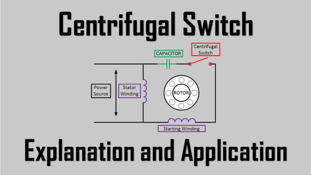
This is where we need the centrifugal switch to disconnect the power from auxiliary windings. Observe the circuit below:

Looking at the circuit above will make you understand instantly what we are talking about until now.
The capacitor is used to shift the phase from power source to auxiliary windings.
The centrifugal switch is to control when we energize the starting windings or de-energize it.
When We Don’t Need Centrifugal Switch
There is another type of split-phase induction motor, it is Capacitor-Start Capacitor-Run Split-Phase Motor or also known as Two Value Capacitor Motor. This type generally doesn’t have a centrifugal switch to disconnect the power source from the starting winding.
Still, it has two types of windings: stator windings and auxiliary windings to make it run properly. It also has two capacitors and are used as run capacitor and start capacitor.
As the name implies, the start capacitor only operates when the starting phase of the motor. After the motor reaches a specific speed, the run capacitor will take over.

We also have what we know as Permanent Split Capacitor Motor or also known as Single Value Capacitor Motor. This type has a permanent capacitor in it and doesn’t need a centrifugal switch.
It consists of:
- Cage rotor,
- Stator windings,
- Auxiliary windings, and
- One capacitor for starting the motor.
The capacitor is connected in series with auxiliary windings permanently in the circuit.

Centrifugal Switch Applications
Even though the centrifugal switch is not popular, this switch has many applications, mainly on protection and safety to some extent.
Below are some of its applications:
- Protection for overspeed in engines such as motors, generators, etc.
- Can be found in electric dc motors, lifts, conveyors, escalators, etc.
- Household appliances (Dryers, fans, blowers, etc).
- Production engines to detect the loss of speed (could cause material losses).

So perfect explanation. I like even more