One of the most useful and versatile op amp circuits for precision measurement and process control is the instrumentation amplifiers (IA), so-called because of its widespread use in measurement systems. Typical applications of IAs include isolation amplifiers, thermocouple amplifiers, and data acquisition systems.
Instrumentation Amplifiers
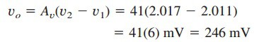
The instrumentation amplifier is an extension of the difference amplifier in that it amplifies the difference between its input signals. An instrumentation amplifier typically consists of three op amps and seven resistors as shown in Figure.(1).
For convenience, the amplifier is shown again in Figure.(1a), where the resistors are made equal except for the external gain-setting resistor RG, connected between the gain set terminals. Figure.(1b) shows its schematic symbol. Figure.(1) shows that

where the voltage gain is

As shown in Figure.(2), the instrumentation amplifier amplifies small differential signal voltages superimposed on larger common-mode voltages. Since the common-mode voltages are equal, they cancel each other.

The IA has three major characteristics:
- The voltage gain is adjusted by one external resistor RG.
- The input impedance of both inputs is very high and does not vary
as the gain is adjusted. - The output vo depends on the difference between the inputs v1 and
v2, not on the voltage common to them (common-mode voltage).
Due to the widespread use of IAs, manufacturers have developed these amplifiers on single-package units. A typical example is the LH0036, developed by National Semiconductor. The gain can be varied from 1 to 1,000 by an external resistor whose value may vary from 100 to 10 kΩ.
Read also : current division rule
Instrumentation Amplifiers Example
In Figure.(1), let R = 10 kΩ, v1 = 2.011 V, and v2 = 2.017 V. If RG is adjusted to 500 Ω, determine: (a) the voltage gain, (b) the output voltage vo.
Solution:
(a) The voltage gain is

(b) The output voltage is