Learning how to design notch filter circuits is not very different from designing band stop filter circuits. Notch filter is one type of the band stop filter, thus these two have similar filtering operation.
Before learning about a notch filter, it won’t hurt to learn about a band stop filter a bit since it will help us greatly.
Like its name, the band stop filter is a filter to filter out a certain band frequency. In other words, this filter is capable of blocking a certain range of frequency to pass to the next part of the circuit.
This frequency selective filter is the opposite of a band pass filter that only passes a certain range of frequency to the next part of the circuit.
This filter is a second-order filter, just as a Band Pass Filter having two cut-off frequencies: -3 dB and half-power point. This frequency range generates a wide stop band bandwidth between two -3 dB points.
Since its characteristic is to block a certain range of frequency, this filter is also known by its second name, Band Reject Filter. The blocked range of frequency is known as the stop band of this filter.
This filter is used to pass any frequency from 0 Hz (DC signal) to the first cut-off frequency (fL) and second cut-off frequency (fH) to higher frequencies. Any frequency between these two cut-off frequencies (fL and fH) will be blocked or filtered out.
For another good information, we can easily make this filter by combining a low pass filter and a high pass filter. This way we can filter out the “middle” range of frequency between the cut-off frequencies of LPF and HPF.
Observe the block diagram below for better understanding.

We can draw their exact circuit to show us their difference in circuit configuration.
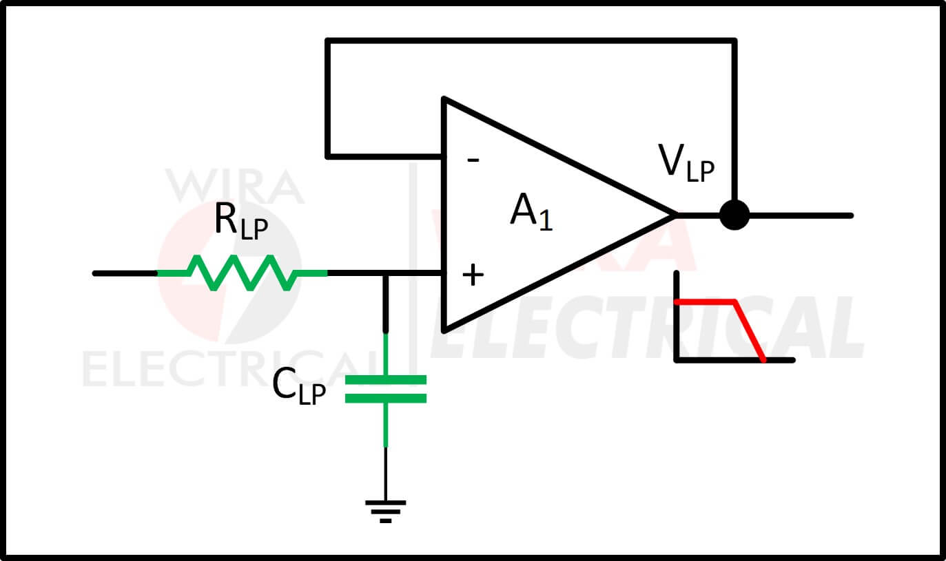
First, we need a Low Pass Filter (LPF) circuit.
Next, we need a High Pass Filter (HPF) circuit.

Lastly, we will combine these two with a summing amplifier.

Combining these three in one circuit results in

Since we combined two filters that each have their own cut-off frequency, a Band Pass Filter has two cut-off frequencies. Any frequency ranging between two cut-off frequencies of our BPF will be blocked.
Observe the graph below.
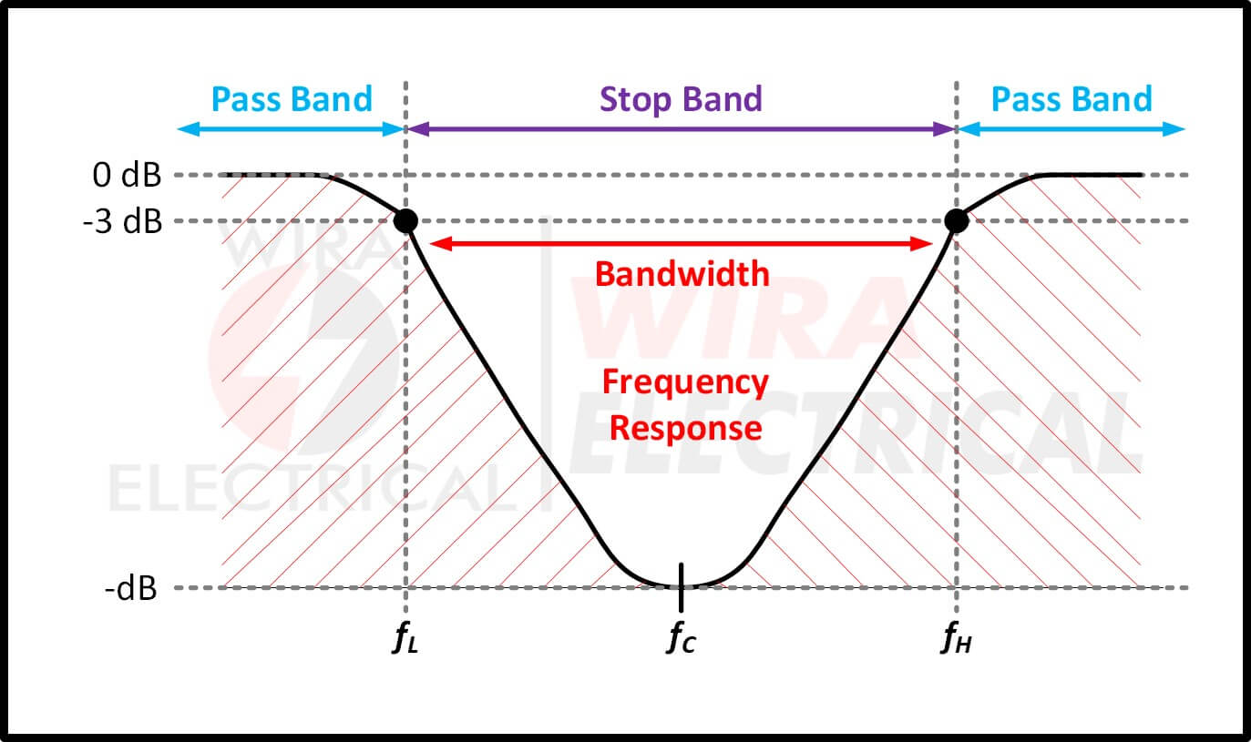
From the graph above, we can conclude that a BPF has three cut-off frequencies:
- Low cut-off frequency (fL) from LPF,
- High cut-off frequency (fH) from HPF, and
- Center cut-off frequency.
Two pass frequencies:
![]()
One block frequency:
![]()
The center frequency of our band stop filter can be calculated from
![]()
What is a Notch Filter
After you observe the frequency response graph of a band stop filter above, you can see that we have that “big” band in the middle. We can make this filter have a narrower band to make it operate more precisely.
Basically, a notch filter is a band stop filter with narrower stop band, highly attenuated over a few Hertz.
The other name of a Notch Filter is Narrow Band Stop Filter. This filter is very selective to its filtering, thus can be used to select a precise frequency to block from the rest of the circuit.
Observe the frequency response graph below

Having this filter in the circuit, we can eliminate any frequency range with a lot more precision. Of course, relying on the operational amplifier will give us better results to get a narrow notch and high level attenuation.
The width of our notch band is calculated by the selectivity Q as we calculate resonance frequency peak of an RLC circuit.
How to Design Notch Filter
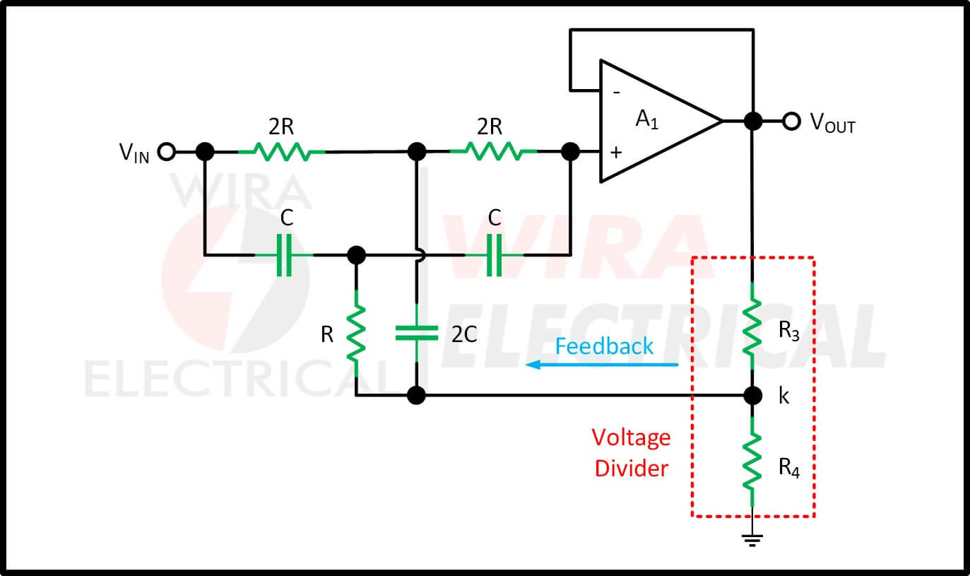
Now we will try to understand the notch filter design. The most common notch filter design is the twin T notch filter. Like what its name implies, it uses a pair of parallel T configurations consisting of RC branches.

Like what we discussed above, a band stop filter or notch filter must consist of a low pass filter and a high pass filter. On the notch filter design above, the half top is the low pass filter while the half bottom is the high pass filter.
- Low pass filter: upper T configuration with a resistor 2R and a capacitor C.
- High pass filter: lower T configuration with a resistor R and a capacitor 2C.
The maximum attenuation or Notch Frequency (fN) or cut-off frequency notch filter can be calculated by
![]()
To generate a higher level attenuation and narrow notch, we will deploy an operational amplifier at the output and tweak it a bit to have a feedback path. We make a notch filter circuit from a twin T filter configuration and an op-amp along with its feedback path. Our final notch filter circuit will be
Notch Filter Circuit Design Calculation with Feedback
Our next task is to make this “feedback” work properly. Here we can use another op-amp to fulfill the role. We deploy the op-amp right after the voltage divider network that acts as the feedback input terminal.

Now we will calculate every variable in the circuit. Assume that we want to have:
- Center notch frequency (fN) at 2 kHz.
- 3 db bandwidth at 400 Hz.
The only known variable is the capacitor with 1 uF capacitance (C) and this is enough for us to solve other parameters completely.
Now follow the steps of notch filter calculation below.
1. Calculating the value of R with the known value of capacitance of 1 uF
2. Calculating the selective value of Q
![]()
3. Calculating the feedback value of k.

4. Calculating the resistors R3 and R4
Assume that we have R4 with 1 kΩ, then

5. Calculating the value of notch depth measured in dB

6. Put every known variables in the circuit

Notch Filter Circuit Application
Even though a notch filter circuit is a special type of a band stop filter, it still has a lot of applications such as:
- The signal in communication electronics is distorted due to some harmonics (noise), which causes the original signal to interfere with the noise signal and results in output error. To get rid of these undesirable harmonic frequencies, notch filters are used.
- Musicians utilize these filters in high-end audio equipment including graphic equalizers, synthesizers, and PA systems.
- Notch filters are also used in telephone technology to improve DSL internet service performance and reduce telephone line noise (harmonics).
- Electric guitar amplifiers frequently employ notch filters as well. In actuality, the electric guitar emits a 60 Hz “hum.” Then, in order to boost the signal generated by the guitar amplifier and make it the greatest equipment, this filter is utilized to eliminate that “hum” by rejecting 60 Hz. Additionally, these are utilized in acoustic applications such as bass instrument amplifiers, mandolins, etc.
- Additionally, optical communication systems employ it. The Raman Spectroscopy is the best illustration. There might be some light frequencies at the end of the optical cable that interfere and cause distortions in the light beam. Then, the narrow band-stop filters get rid of these distortions.
- In order to reduce noise, these filters are generally favored in image and signal processing.
- Additionally, it is utilized to lessen the static on radios, which are frequently used in our daily lives.
- Additionally, these filters are utilized in the medical industry in biomedical instruments like ECGs to remove lines.
Notch Filter Summary
With little to no attenuation at all other frequencies, notch filters are engineered to offer strong attenuation at and near a single frequency. To achieve a deep notch, notch filters use a twin-T parallel resistance-capacitance (RC) network. By feeding back some of the output to the junction of the two tees, higher values of Q can be produced.
The junction of the resistance and capacitance in the two tees can be connected to the central point of a voltage divider network connected to the filter’s output signal to make the notch filter more selective and with a range of Q values. At the notch frequency, a well-designed notch filter can attenuate signals by more than -60dB.
When used to reject or attenuate a particular frequency or harmonic content that produces electrical noise, such as mains hum inside a circuit, notch filters can be extremely discriminating.